|
1
|
INSPECT FOR MALFUNCTION IN BCM POWER SUPPLY CIRCUIT OR ELSEWHERE
• Did any of the following items operate during the keyless entry system operation inspection?
-
― All doors lock/unlock
― Hazard wiring light flashes
|
Yes
|
Go to the next step.
|
|
No
|
Inspect the connection of the BCM connectors, and go to Step 4.
|
|
2
|
INSPECT FOR MALFUNCTION IN KEY REMINDER SWITCH OR ELSEWHERE
• Did the following item operate during the keyless entry system operation inspection?
-
― All doors lock/unlock
|
Yes
|
Go to the next step.
|
|
No
|
Go to Step 9.
|
|
3
|
INSPECT FOR MALFUNCTION IN DOOR LOCK ACTUATOR OR ELSEWHERE
• Did the following item operate during the keyless entry system operation inspection?
-
― Hazard warning light flashes
|
Yes
|
Go to the next step.
|
|
No
|
Go to Step 11.
|
|
*4
|
INSPECT BCM POWER SUPPLY CIRCUIT
• Are the BCM power supply and voltage normal?
-
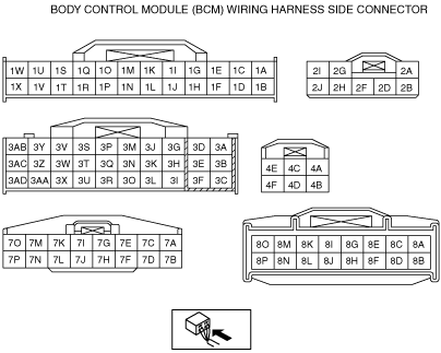
― IG1 signal (terminal 3AB, 4A)
― B+ signal (terminal 2D, 2J, 4B, 4C)
|
Yes
|
Go to the next step.
|
|
No
|
• Inspect for burnt fuse.
• Inspect the power supply system wiring harness for an open or short circuit.
• Then go to Step 14.
|
|
*5
|
INSPECT BCM GROUND CIRCUIT
• Is the BCM ground voltage normal?
-
― 0V (terminal 1V, 2A)
|
Yes
|
Go to the next step.
|
|
No
|
Inspect the ground system wiring harness for open circuit.
Then go to Step 14.
|
|
*6
|
INSPECT door latcu switch SIGNAL
• Monitor following BCM (door latcu switch) PID using the M-MDS.
-
― TR/LG_SW (Trunk lid/liftgate latch switch)
― DRSW_P (Passenger’s door latch switch)
― DRSW_D (Driver’s door latcu switch)
• Are monitored PID values normal?
|
Yes
|
Go to the next step.
|
|
No
|
• Inspect for open or short circuit in wiring harness between BCM and suspected door latch/trunk lid (4SD)/liftgate (5HB) latch switch.
-
― If wiring harness is normal, inspect suspect door latch/trunk lid (4SD)/liftgate (5HB) latch switch.
― If wiring harness malfunction, repair or replace wiring harness, then go to Step 14.
|
|
*7
|
INSPECT DOOR LATCU SWITCH SIGNAL VOLTAGE
• Are the wiring harness between the BCM and each door latch switch normal?
-
― Inspect each terminal (8B, 8D, 8F, 8H) under the following conditions.
• Door/trunk/liftgate closed : B+
• Door/trunk/liftgate open: 2.0V or less
|
Yes
|
Go to the next step.
|
|
No
|
• Inspect the door latcu switch.
• Inspect the door latcu switch system wiring harness for a short circuit.
• Then go to Step 14.
|
|
8
|
INSPECT KEY REMINDER SWITCH
• Is the key reminder switch normal? ON: 12V
OFF: 0V
|
Yes
|
Replace the BCM.
|
|
No
|
Replace the key reminder switch, then go to Step 14.
|
|
*9
|
INSPECT IF MALFUNCTION IS IN DOOR LOCK ACTUATOR, BCM GROUND CIRCUIT OR ELSEWHERE
• Measure the voltage at the BCM terminals 7I, 7M and 7K while operating the transmitter.
-
― All doors locked: 1.0 V or less → B+→ 1.0 V or less (Normal lock : 7I terminal)(Double lock : 7M terminal)
― All doors unlocked : 1.0 V or less → B+→ 1.0 V or less (7K terminal)
• Is the voltage as above?
|
Yes
|
Go to the next step.
|
|
No
|
• Inspect the wiring harness between BCM and the door lock actuator for an open or short circuit.
• Inspect the door lock actuator.
• Then go to Step 14.
|
|
10
|
INSPECT DOOR LOCK LINKAGE
• Operate the door lock knob and verify the door locks and unlock manually.
• Does every door lock system work?
|
Yes
|
Go to step 12.
|
|
No
|
Inspect the door lock linkage then go to Step 14.
|
|
*11
|
INSPECT FOR MALFUNCTION IN THEFT-DETERRENT SYSTEM OR ELSEWHERE
• Is the theft-deterrent system equipped?
|
Yes
|
Go to the next step.
|
|
No
|
Go to step 13.
|
|
12
|
INSPECT BONNET SWITCH AND TRUNK/LIFTGATE SIGNAL
• Monitor following BCM PID using the M-MDS.
-
― TR/LG_SW (liftgate/trunk latch switch)
― HOOD_SW (bonnet latch switch)
• Are monitored PID values ON (open)?
|
Yes
|
Normal operation (Hazard warning light flashing on vehicles with theft-deterrent system operates in conjunction with theft-deterrent system).
|
|
No
|
Go to the next step.
|
|
*13
|
INSPECT TURN LIGHT SIGNAL CIRCUIT
• Measure voltage at the BCM terminals 3J, 3I, 1P (right side turn signal), 8K, 8L and 1R (left side turn signal) while operating hazard and/or turn signal on.
• Are the terminal voltages are alternated between 1.0V or less and B+?
|
Yes
|
Verify the malfunction symptom again.
|
|
No
|
• Inspect the wiring harnesses between the BCM and each turn light for a short circuit.
• Inspect each turn light.
• If these items are normal, replace the BCM.
|
|
*14
|
REINSPECT MALFUNCTION SYMPTOM AFTER REPAIR
• Does the keyless entry system operate properly?
|
Yes
|
Troubleshooting completed.
Explain repairs to the customer.
|
|
No
|
Reinspect the malfunction symptoms, then repeat from Step 1 if the malfunction recurs.
|