LIFTGATE LOCK MOTOR INSPECTION
id091400453200
1. Verify that the full-latch switch, half-latch switch, and return switch are normal.
(See LIFTGATE LATCH POSITION SWITCH INSPECTION.)
2. Verify that the liftgate auto closure control module terminal 1A, terminal 2G power supply are normal.
(See LIFTGATE AUTO CLOSURE CONTROL MODULE INSPECTION.)
-
• If it cannot be verified, perform the following inspection or repairs:
-
― Open or short circuit between the liftgate auto closure control module terminal 1A and BCM terminal 7C
― Open or short circuit between the liftgate auto closure control module terminal 2G and BCM terminal 7B
-
Note
-
• If performed continuously, the motor protection circuit will stop the liftgate lock motor operation temporarily.
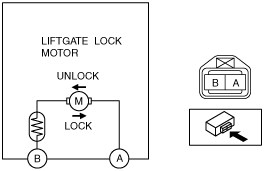
3. Perform the following operation and verify the terminal voltage of the liftgate lock motor.
-
Lock operation; (pull-in operation;):
-
• Move the liftgate latch to the half-latch position using a flathead screwdriver.
-
Unlock operation (unlatch operation):
-
• Press the open switch.
-
― If the liftgate latch and lock motor cannot operate according to the table during the lock operation, replace it.
― If the liftgate latch and lock motor cannot operate according to the table during the unlock operation, and after it has been verified that the open switch is operating normally, replace the liftgate and lock motor.
|
Lock motor operation
|
Terminal
|
|
A
|
B
|
|
LOCK
|
Ground
|
B+
|
|
UNLOCK
|
B+
|
Ground
|