 |
am6zzw00001832
PARKING SENSOR CONTROL MODULE INSPECTION
id092200775300
1. Remove the parking sensor control module with the connector connected. (See PARKING SENSOR CONTROL MODULE REMOVAL/INSTALLATION.)
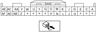
2. Measure the voltage at each terminal is as indicated in the Terminal Voltage Tables.
Terminal Voltage Table (Reference)
am6zzw00001832
|
|
Terminal |
Signal name |
Connected to |
Measured item |
Test condition |
Voltage(V) |
Inspection item |
|
|---|---|---|---|---|---|---|---|
|
A
|
Ultrasonic sensor
|
Back sensor (left)
|
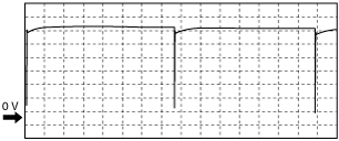
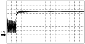
Wave profile
|
• Back sensor (left)
• Related wiring harnesses
|
|||
|
B
|
Terminal for measuring the front buzzer terminal voltage (no auxiliary wiring harness to connect to the external devices)
|
Voltage
|
Switch the ignition to ON
|
Parking sensor switch ON and buzzer stopped
|
B+
|
Parking sensor control module
|
|
|
Parking sensor switch ON and buzzer sounding
|
1.0 or less
|
||||||
|
C
|
Ultrasonic sensor
|
Back sensor (right)
|
Wave profile
|
• Back sensor (right)
• Related wiring harnesses
|
|||
|
D
|
—
|
—
|
—
|
—
|
—
|
—
|
—
|
|
E
|
Ultrasonic sensor
|
Rear corner sensor (left)
|
Wave profile
|
• Rear corner sensor (left)
• Related wiring harnesses
|
|||
|
F
|
—
|
—
|
—
|
—
|
—
|
—
|
—
|
|
G
|
Ultrasonic sensor
|
Rear corner sensor (right)
|
Wave profile
|
• Rear corner sensor (right)
• Related wiring harnesses
|
|||
|
H
|
GND
|
Rear/Back sensor
|
Voltage
|
Under any condition
|
Under any condition
|
1.0 or less
|
• Rear corner sensor (right)
• Rear corner sensor (left)
• Back sensor (right)
• Back sensor (left)
• Related wiring harnesses
|
|
I
|
Ultrasonic sensor
|
Front corner sensor (left)
|
Wave profile
|
• Front corner sensor (left)
• Related wiring harnesses
|
|||
|
J
|
GND
|
Front corner sensor (left)
|
Voltage
|
Under any condition
|
Under any condition
|
1.0 or less
|
• Front corner sensor (left)
• Related wiring harnesses
|
|
K
|
Ultrasonic sensor
|
Front sensor (left)
|
Wave profile
|
• Front sensor (left)
• Related wiring harnesses
|
|||
|
L
|
GND
|
Front sensor (left)
|
Voltage
|
Under any condition
|
Under any condition
|
1.0 or less
|
• Front sensor (left)
• Related wiring harnesses
|
|
M
|
Ultrasonic sensor
|
Front sensor (right)
|
Wave profile
|
• Front sensor (right)
• Related wiring harnesses
|
|||
|
N
|
GND
|
Front sensor (right)
|
Voltage
|
Under any condition
|
Under any condition
|
1.0 or less
|
• Front sensor (right)
• Related wiring harnesses
|
|
O
|
Ultrasonic sensor
|
Front corner sensor (right)
|
Wave profile
|
• Front corner sensor (right)
• Related wiring harnesses
|
|||
|
P
|
GND
|
Front corner sensor (right)
|
Voltage
|
Under any condition
|
Under any condition
|
1.0 or less
|
• Front corner sensor (right)
• Related wiring harnesses
|
|
Q
|
Ultrasonic sensor ground
|
Body ground
|
Voltage
|
Under any condition
|
Under any condition
|
1.0 or less
|
Related wiring harnesses
|
|
R
|
—
|
—
|
—
|
—
|
—
|
—
|
—
|
|
S
|
—
|
—
|
—
|
—
|
—
|
—
|
—
|
|
T
|
—
|
—
|
—
|
—
|
—
|
—
|
—
|
|
U
|
IG
|
Parking sensor switch
|
Voltage
|
Switch the ignition to ON
|
Parking sensor switch ON
|
B+
|
• Parking sensor switch
• Related wiring harnesses
|
|
Parking sensor switch OFF
|
1.0 or less
|
||||||
|
V
|
—
|
—
|
—
|
—
|
—
|
—
|
—
|
|
W
|
R position
|
Back-up light switch
|
Voltage
|
Ignition switch
ON and parking sensor switch ON
|
Shift lever is in R position
|
6.0 or more
|
• Back-up light switch
• BCM
• Related wiring harnesses
|
|
Shift lever is in position other than R
|
2.0 or less
|
||||||
|
X
|
—
|
—
|
—
|
—
|
—
|
—
|
—
|
|
Y
|
Vehicle speed
|
Instrument cluster
|
Wave profile
|
Rectangular wave pattern is displayed while driving
|
Speed signal is input: ON
|
6.0 or more
|
• Instrument cluster
• Related wiring harnesses
|
|
Speed signal is not input: OFF
|
Open or 5.0 or more
|
||||||
|
Z
|
Parking sensor buzzer (rear)
|
Parking sensor buzzer (rear)
|
Voltage
|
Ignition switch ON and parking sensor switch ON
|
Parking sensor switch ON and buzzer stopped
|
B+
|
• Parking sensor buzzer (rear)
• Related wiring harnesses
|
|
Parking sensor switch ON and buzzer sounding
|
1.0 or less
|
||||||
|
AA
|
Parking brake switch
|
Parking brake switch
|
Voltage
|
Ignition switch ON and parking sensor switch ON
|
Parking brake is activated
|
2.0 or less
|
• Parking brake switch
• Related wiring harnesses
|
|
Parking brake is not activated
|
5.0 or more
|
||||||
|
AB
|
Indicator
|
Parking sensor switch
|
Voltage
|
Switch the ignition to ON
|
Parking sensor switch is ON and parking sensor indicator light is not illuminated
|
B+
|
• Parking sensor switch
• Related wiring harnesses
|
|
Parking sensor switch is ON and parking sensor indicator light is illuminated
|
1.0 or less
|
||||||
|
Parking sensor switch is OFF
|
1.0 or less
|
||||||
|
AC
|
Headlight washer
|
Headlight washer switch
|
Voltage
|
Ignition switch ON and parking sensor switch ON
|
Headlight washer switch is OFF
|
5.0 or more
|
• Headlight washer switch
• Related wiring harnesses
|
|
Headlight washer switch is ON
|
2.0 or less
|
||||||
|
AD
|
Trailer
|
Trailer switch
|
Voltage
|
Ignition switch ON and parking sensor switch ON
|
Trailer switch is ON
|
2.0 or less
|
• Trailer switch
• Related wiring harnesses
|
|
Trailer switch is OFF
|
5.0 or more
|
||||||
|
AE
|
Headlight
|
Light switch
|
Voltage
|
Ignition switch ON and parking sensor switch ON
|
Light switch is OFF
|
5.0 or more
|
• Light switch
• Related wiring harnesses
|
|
Light switch is ON
|
2.0 or less
|
||||||
|
AF
|
Tow-bar
|
Tow-bar switch
|
Voltage
|
Ignition switch ON and parking sensor switch ON
|
Tow-bar switch is ON
|
2.0 or less
|
• Tow-bar switch
• Related wiring harnesses
|
|
Tow-bar switch is OFF
|
5.0 or more
|
||||||
Generated Pulse (reference)
am6zzw00002748
|
am6zzw00002749
|
|
Condition
|
Shift lever
|
Vehicle speed
|
Terminal
|
|||||||
|
Corner corner sensor (right)
|
Corner corner sensor (left)
|
Front sensor (right)
|
Front sensor (left)
|
Rear corner sensor (right)
|
Rear corner sensor (left)
|
Back sensor (right)
|
Back sensor (left)
|
|||
|
OFF
|
Except R position
|
10—15 km/h {6.3—9.3 mph} or less
|
O—Q
|
I—Q
|
M—Q
|
K—Q
|
—
|
—
|
—
|
—
|
|
R position
|
10—15 km/h {6.3—9.3 mph} or less
|
O—Q
|
I—Q
|
—
|
—
|
G—Q
|
E—Q
|
C—Q
|
A—Q
|
|