|
1
|
VERIFY FREEZE FRAME DATA HAS BEEN RECORDED
• Has FREEZE FRAME DATA been recorded?
|
Yes
|
Go to the next step.
|
|
No
|
Record the FREEZE FRAME DATA on the repair order, then go to the next step.
|
|
2
|
VERIFY RELATED SERVICE INFORMATION AVAILBAILITY
• Verify related Service information availability.
• Is any related Service information available?
|
Yes
|
Perform repair or diagnosis according to thavailable Service information.
• If the vehicle is not repaired, go to the next step.
|
|
No
|
Go to the next step.
|
|
3
|
VERIFY RELATED PENDING AND STORED DTCS
• Turn the ignition switch off, then to the ON position (engine off).
• Verify the pending and stored DTCs using the M-MDS.
• Is any DTC present?
|
Yes
|
Go to the applicable DTC inspection.
|
|
No
|
Go to the next step.
|
|
4
|
IDENTIFY TRIGGER DTC FOR FREEZE FRAME DATA
• Is the DTC P2101 on FREEZE FRAME DATA?
|
Yes
|
Go to the next step.
|
|
No
|
Go to the troubleshooting procedures for DTC on FREEZE FRAME DATA.
|
|
5
|
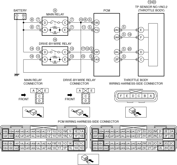
INSPECT PCM CONNECTOR FOR POOR CONNECTION
• Turn the ignition switch off.
• Disconnect the PCM connector.
• Inspect for poor connection (such as damaged, pulled out terminals, corrosion).
• Is there any malfunction?
|
Yes
|
Repair or replace the terminal, then go to Step 21.
|
|
No
|
Go to the next step.
|
|
6
|
INSPECT MAIN RELAY OUTPUT VOLTAGE
• Turn the ignition switch off.
• Connect the PCM connector.
• Turn the ignition switch to the ON position (engine off).
• Measure the voltage between PCM terminal 1BE (wiring harness-side) and body ground.
• Is the voltage B+?
|
Yes
|
Go to Step 12.
|
|
No
|
Go to the next step.
|
|
7
|
INSPECT MAIN RELAY CONNECTOR FOR POOR CONNECTION
• Turn the ignition switch off.
• Disconnect the main relay connector.
• Inspect for poor connection (such as damaged, pulled out terminals, corrosion).
• Is there any malfunction?
|
Yes
|
Repair or replace the terminal, then go to Step 21.
|
|
No
|
Go to the next step.
|
|
8
|
INSPECT POWER SUPPLY FOR CONTROL CIRCUIT OF MAIN RELAY
• Turn the ignition switch to the ON position (engine off).
• Measure the voltage between following circuit:
-
― Main relay terminal A (wiring harness-side) and body ground
― Main relay terminal D (wiring harness-side) and body ground
• Is the voltage B+?
|
Yes
|
Go to the next step.
|
|
No
|
Repair or replace the wiring harness for a possible open circuit, then go to Step 21.
|
|
9
|
INSPECT MAIN RELAY
• Inspect the main relay.
• Is there any malfunction?
|
Yes
|
Replace the main relay, then go to Step 21.
|
|
No
|
Go to the next step.
|
|
10
|
INSPECT POWER CIRCUIT FOR OPEN CIRCUIT
• Turn the ignition switch off.
• Disconnect the main relay connector and the PCM connector.
• Inspect for continuity between main relay terminal C (wiring harness-side) and PCM terminal 1BE (wiring harness-side).
• Is there continuity?
|
Yes
|
Go to the next step.
|
|
No
|
Repair or replace the wiring harness for a possible open circuit, then go to Step 21.
|
|
11
|
INSPECT CONTROL CIRCUIT FOR OPEN CIRCUIT
• Turn the ignition switch off.
• Inspect for continuity between main relay terminal E (wiring harness-side) and PCM terminal 1Q (wiring harness-side).
• Is there continuity?
|
Yes
|
Go to the next step.
|
|
No
|
Repair or replace the wiring harness for a possible open circuit, then go to Step 22.
|
|
12
|
INSPECT DRIVE-BY-WIRE RELAY OUTPUT VOLTAGE
• Turn the ignition switch to the ON position (engine off).
• Measure the voltage between PCM terminal 1BF (wiring harness-side) and body ground.
• Is the voltage B+?
|
Yes
|
Go to Step 19.
|
|
No
|
Go to the next step.
|
|
13
|
INSPECT POOR CONNECTION OF DRIVE-BY-WIRE RELAY CONNECTOR
• Turn the ignition switch off.
• Disconnect the drive-by-wire relay connector.
• Inspect for poor connection (such as damaged, pulled out terminals, corrosion).
• Is there any malfunction?
|
Yes
|
Repair or replace the terminal, then go to Step 21.
|
|
No
|
Go to the next step.
|
|
14
|
INSPECT POWER SUPPLY OF DRIVE-BY-WIRE RELAY
• Turn the ignition switch to the ON position (engine off).
• Measure the voltage between drive-by-wire relay terminal D (wiring harness-side) and body ground.
• Is the voltage B+?
|
Yes
|
Go to the next step.
|
|
No
|
Repair or replace the wiring harness for a possible open circuit, then go to Step 21.
|
|
15
|
INSPECT POWER SUPPLY FOR CONTROL CIRCUIT OF DRIVE-BY-WIRE RELAY
• Turn the ignition switch to the ON position (engine off).
• Measure the voltage between drive-by-wire relay terminal E (wiring harness-side) and body ground.
• Is the voltage B+?
|
Yes
|
Go to the next step.
|
|
No
|
Repair or replace the wiring harness for a possible open circuit, then go to Step 21.
|
|
16
|
INSPECT DRIVE-BY-WIRE RELAY
• Inspect the drive-by-wire relay.
• Is there any malfunction?
|
Yes
|
Replace the drive-by-wire relay, then go to Step 21.
|
|
No
|
Go to the next step.
|
|
17
|
INSPECT POWER CIRCUIT FOR OPEN CIRCUIT
• Turn the ignition switch off.
• Inspect for continuity between drive-by-wire relay terminal C (wiring harness-side) and PCM terminal 1BF (wiring harness-side).
• Is there continuity?
|
Yes
|
Go to the next step.
|
|
No
|
Repair or replace the wiring harness for a possible open circuit, then go to Step 21.
|
|
18
|
INSPECT CONTROL CIRCUIT FOR OPEN CIRCUIT
• Turn the ignition switch off.
• Inspect for continuity between drive-by-wire relay A (wiring harness-side) and PCM terminal 1BE (wiring harness-side).
• Is there continuity?
|
Yes
|
Go to the next step.
|
|
No
|
Repair or replace the wiring harness for a possible open circuit, then go to Step 21.
|
|
19
|
INSPECT TP SENSOR NO.1 OUTPUT VOLTAGE
• Turn the ignition switch off.
• Connect the PCM connector.
• Turn the ignition switch to the ON position (engine off).
• Inspect the voltage between PCM terminal 2AK (wiring harness-side) and body ground.
• Is the voltage 0.40—0.60 V?
|
Yes
|
Go to the next step.
|
|
No
|
Inspect TP sensor No.1 and the related circuits and terminals.
Repair or replace if necessary, then go to Step 21.
|
|
20
|
INSPECT TP SENSOR NO.2 OUTPUT VOLTAGE
• Turn the ignition switch to the ON position (engine off).
• Inspect the voltage between PCM terminal 2AL (wiring harness-side) and body ground.
• Is the voltage 4.40—4.60 V?
|
Yes
|
Go to the next step.
|
|
No
|
Inspect TP sensor No.2 and the related circuits and terminals.
Repair or replace if necessary, then go to the next step.
|
|
21
|
VERIFY TROUBLESHOOTING OF DTC P2101 COMPLETED
• Make sure to reconnect all disconnected connectors.
• Turn the ignition switch to the ON position (engine off).
• Clear the DTC from the PCM memory using the M-MDS.
• Start the engine and idle it.
• Turn the ignition switch off, then to the ON position (engine off).
• Is the same DTC present?
|
Yes
|
Replace the PCM, then go to the next step.
|
|
No
|
Go to the next step.
|
|
22
|
VERIFY AFTER REPAIR PROCEDURE
• Perform the “AFTER REPAIR PROCEDURE”.
• Is there any DTC present?
|
Yes
|
Go to the applicable DTC inspection.
|
|
No
|
Troubleshooting completed.
|