DTC
C1279, C1280, C1281, C1952, C1959
Combined sensor system
DETECTION CONDITION
• C1279
-
― Variation of the yaw rate value from the combined sensor while the vehicle is stopped or started is not within the specification.
• C1280
-
― Condition 1
-
• The difference between the yaw rate value calculated by each sensor and the yaw rate value from the combined sensor exceeds the specification.
― Condition 2-
• While the vehicle is moving forward, one of the yaw rate values is + and the other is - (yaw rate value calculated from steering angle sensor signal and one from the combined sensor).
-
• C1281
-
― Difference between the two lateral-G values exceeds the specification (one from the combined sensor and one calculated from yaw rate signal from the combined sensor, steering angle sensor signal, and ABS wheel-speed sensor signal).
• C1952
-
― Signal, which indicates low voltage or over voltage, from the combined sensor is continued for 100 ms.
• C1959
-
― Variation of the lateral-G value from the combined sensor is not within the specification.
FAIL-SAFE
• C1279, C1281, C1959
-
― Inhibits TCS control and DSC control, and illuminates DSC indicator light.(If error is detected during a TCS control, inhibits TCS control after finishing the control.)
• C1280
-
― Condition 1
-
• Inhibits TCS control and DSC control, and illuminates DSC indicator light.(If error is detected during a TCS control, inhibits TCS control after finishing the control.)
― Condition 2-
• Inhibits TCS control and DSC control, and illuminates DSC indicator light.(If error is detected during a TCS control, inhibits TCS control after finishing the control. If the following conditions are all met at next system activation, enables (restores) each control and turns each light off.)a. Yaw rate sensor signal exceeds 3 °/sb. Vehicle speed is 70.2 km/h or morec. Difference between yaw rate sensor signal and the yaw rate value calculated by each sensor is within acceptable range
-
• C1952
-
― Inhibits TCS control and DSC control, and illuminates DSC indicator light.(If error is detected during a TCS control, inhibits TCS control after finishing the control. If the signal, which indicate low voltage or over voltage, is eliminated, enables (restores) each control and turns each light off. However, if error is detected again within 180 s after permission (restoring), inhibits each control and illuminates each light until ignition switch is turned off.)
POSSIBLE CAUSE
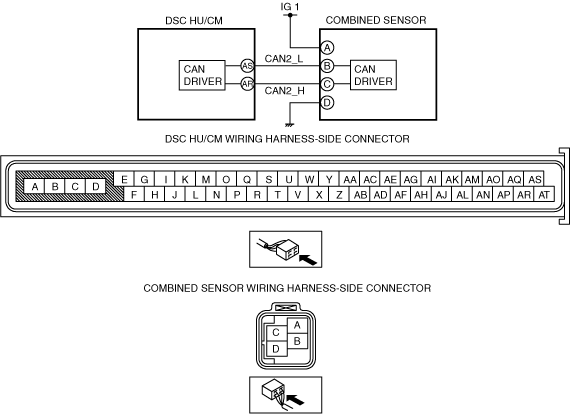
• Poor installation of combined sensor
• Open circuit or short to ground in wiring harness between ignition switch—combined sensor terminal A
• Open circuit in wiring harness between combined sensor terminal D—ground
• Combined sensor malfunction
• Poor connection at connectors (female terminal)