 |
ar8uuw00001511
DSC HU/CM REMOVAL/INSTALLATION
id041500801000
1. Remove the engine cover. (See ENGINE COVER REMOVAL/INSTALLATION [13B-MSP].)
2. Remove the front suspension tower bar. (See FRONT SUSPENSION TOWER BAR REMOVAL/INSTALLATION [MT].) (See FRONT SUSPENSION TOWER BAR REMOVAL/INSTALLATION [AT].)
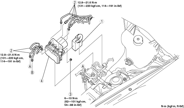
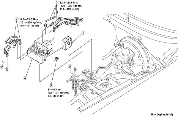
3. Remove in the order indicated in the table.
4. Install in the reverse order of removal.
5. Configurate the DSC HU/CM. (See DSC CONFIGURATION.)
6. After installation, perform the combined sensor initialization procedure. (See COMBINED SENSOR INITIALIZATION PROCEDURE.)
7. After installation, perform the steering angle sensor initialization procedure. (See STEERING ANGLE SENSOR INITIALIZATION PROCEDURE.)
L.H.D.
ar8uuw00001511
|
|
1
|
DSC HU/CM connector
|
|
2
|
Brake pipe
(See Brake Pipe Removal Note.)
(See Brake Pipe Installation Note.)
|
|
3
|
Nut
|
|
4
|
DSC HU/CM
|
R.H.D.
ar8wzw00000323
|
|
1
|
DSC HU/CM connector
|
|
2
|
Brake pipe
(See Brake Pipe Removal Note.)
(See Brake Pipe Installation Note.)
|
|
3
|
Nut
|
|
4
|
DSC HU/CM
|
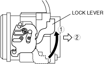
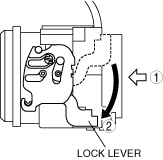
DSC HU/CM Connector Removal Note
1. Pull the lock lever up in the direction of the arrow.
ar8uuw00001248
|
2. Pull the connector toward the vehicle rear and remove it.
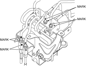
Brake Pipe Removal Note
1. Place an alignment mark on the brake pipe and DSC HU/CM.
ar8uuw00001249
|
2. Apply protective tape to the connector to prevent brake fluid from entering.
3. Remove the brake pipe.
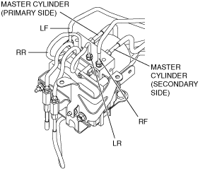
Brake Pipe Installation Note
1. Align the marks made before removal and install the brake pipe to the DSC HU/CM and brake pipe joint referring to the figure.
ar8uuw00001250
|
2. Tighten the brake pipe to the specified torque using the commercially available flare nut wrench.
DSC HU/CM Connector Installation Note
1. After connecting the connector, verify that the lock lever is completely pushed in.
ar8uuw00001251
|