 |
ar8wzw00001202
VEHICLE SPEED SENSOR (VSS) INSPECTION [SJ6A-EL]
id051311252600
1. Remove the engine cover. (See ENGINE COVER REMOVAL/INSTALLATION [13B-MSP].)
2. Remove the battery cover.
3. Disconnect the negative battery cable.
4. Remove the front tunnel member.
5. Remove the rear tunnel member.
6. Remove the catalytic converter. (See EXHAUST SYSTEM REMOVAL/INSTALLATION [13B-MSP].)
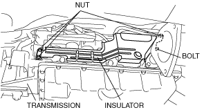
7. Remove the insulator.
ar8wzw00001202
|
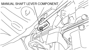
8. Mark the manual shaft lever component as shown in the figure.
ar8wzw00001203
|
9. Separate the manual shaft lever component from selector lever.
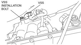
10. Disconnect the VSS connector.
e5u513zw5033
|
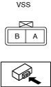
11. Measure the resistance between the VSS terminals.
e5u513zw5062
|
12. Connect the VSS connector.
13. Align the mark of the manual shaft lever component as shown in the figure.
ar8wzw00001203
|
14. Install the manual shaft lever component installation nut.
15. Install the insulator.
16. Install the catalytic converter. (See EXHAUST SYSTEM REMOVAL/INSTALLATION [13B-MSP].)
17. Install the rear tunnel member.
18. Install the front tunnel member.
19. Connect the negative battery cable.
20. Install the battery cover.
21. Install the engine cover. (See ENGINE COVER REMOVAL/INSTALLATION [13B-MSP].)