 |
ar8uuw00001718
EXHAUST SYSTEM REMOVAL/INSTALLATION [13B-MSP]
id0115z2800200
1. Remove the engine cover. (See ENGINE COVER REMOVAL/INSTALLATION [13B-MSP].)
2. Remove the battery cover. (See BATTERY REMOVAL/INSTALLATION [13B-MSP].)
3. Disconnect the negative battery cable. (See BATTERY REMOVAL/INSTALLATION [13B-MSP].)
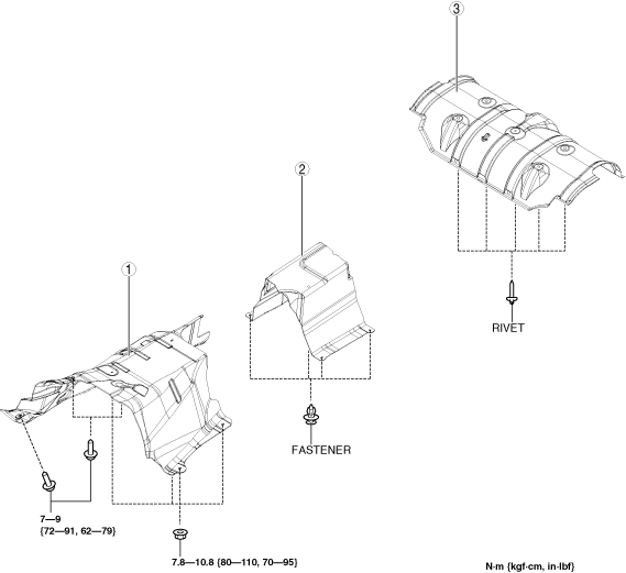
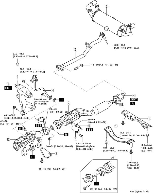
4. Remove in the order indicated in the table.
5. Remove the insulator. (See Exhaust Insulator Removal/Installation Note.)
6. Install in the reverse order of removal.
ar8uuw00001718
|
|
1
|
Tunnel member
|
|
2
|
Main silencer
|
|
3
|
Middle pipe
|
|
4
|
Seal ring
(See Seal Ring Removal Note.)
(See Seal Ring Installation Note.)
|
|
5
|
Protector
|
|
6
|
HO2S
|
|
7
|
TWC
|
|
8
|
Bracket
|
|
9
|
A/F sensor
|
|
10
|
AIR pipe
|
|
11
|
Engine mount bracket (RH)
|
|
12
|
Exhaust manifold
|
Exhaust Insulator Removal/Installation Note
1. Remove in the order indicated in the table.
2. Install in the reverse order of removal.
ar8uuw00001719
|
|
1
|
Insulator (front)
|
|
2
|
Insulator (middle)
|
|
3
|
Insulator (rear)
(See Rivet removal note.)
|
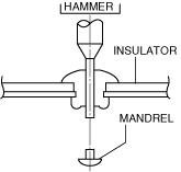
Rivet removal note
1. Push out the mandrel using a hammer and punch (2—2.8 mm {0.08—0.11 in} diameter).
ar8uuw00001478
|
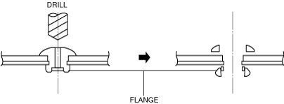
2. Remove the flange using a drill (5 mm {0.20 in} drill bit).
ar8uuw00001479
|
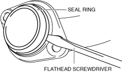
Seal Ring Removal Note
1. Remove the seal ring using a flathead screwdriver being careful not to damage the pipe.
ar8uuw00001480
|
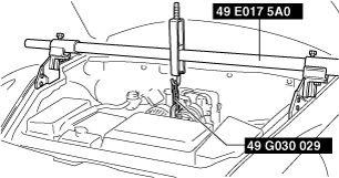
Engine Mount Bracket (RH) Removal Note
1. Remove the front wheel and tire. (See GENERAL PROCEDURES (SUSPENSION).)
2. Remove the front suspension tower bar. (See FRONT SUSPENSION TOWER BAR REMOVAL/INSTALLATION [MT].)(See FRONT SUSPENSION TOWER BAR REMOVAL/INSTALLATION [AT].)
3. Attach the SST and support the engine.
ar8uuw00001481
|
4. Remove the engine mount rubber (LH) installation nut.
5. Remove in the order indicated in the table.
ar8uuw00001482
|
|
1
|
Engine mount rubber (RH)
|
|
2
|
Engine mount bracket (RH)
|
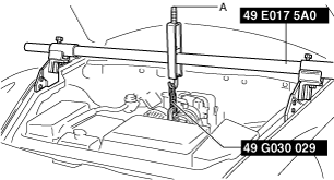
Engine mount rubber (RH) removal note
1. Tighten the A part indicated in the figure, and then pull up the engine to remove the engine mount rubber (RH).
ar8uuw00001720
|
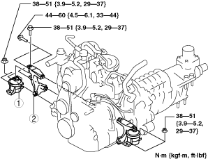
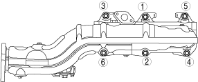
Exhaust Manifold Removal Note
1. Remove the under cover.
2. Loosen the bolts in the order shown in the figure.
ar8uuw00000457
|
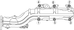
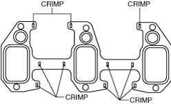
Exhaust Manifold Installation Note
ar8uuw00001484
|
1. Tighten the bolts in the order shown in the figure.
ar8uuw00000460
|
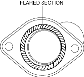
Middle Pipe, Three Way Catalytic Converter (TWC) Installation Note
1. Spray carbon remover (TB6601 or equivalent) on the flared section of the exhaust pipe.
2. Remove the carbon adhering to the flared section shown in the figure using a nylon brush or sandpaper (No.400 or equivalent).
ar8uuw00002178
|
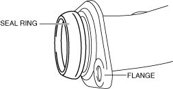
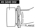
Seal Ring Installation Note
1. Temporarily install the seal ring to the pipe so that the seal ring is even with the flange.
ar8uuw00001485
|
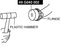
2. Install the SST to the seal ring so that the SST is even with the flange.
ar8uuw00001486
|
3. Press in the seal ring by tapping the SST using a plastic hammer until the seal ring contacts the flange.
ar8uuw00001487
|
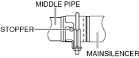
Main Silencer Installation Note
1. Install the main silencer so that the stopper is at the position shown in the figure.
ar8uuw00001488
|