|
ar8uuw00000299
TRANSMISSION RANGE (TR) SWITCH REMOVAL/INSTALLATION [SJ6A-EL]
id051311710200
1. Remove the engine cover. (See ENGINE COVER REMOVAL/INSTALLATION [13B-MSP].)
2. Remove the battery cover.
3. Disconnect the negative battery cable.
4. Remove the front tunnel member.
5. Remove the rear tunnel member.
6. Remove the catalytic converter. (See EXHAUST SYSTEM REMOVAL/INSTALLATION [13B-MSP].)
7. Remove the insulator.
ar8uuw00000299
|
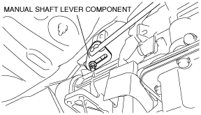
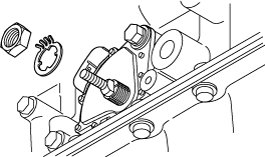
8. Mark the manual shaft lever component as shown in the figure.
ar8uuw00000300
|
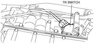
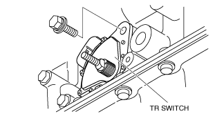
9. Separate the manual shaft lever component from selector lever.
10. Disconnect the TR switch connector.
ar8uuw00000301
|
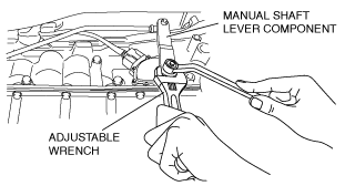
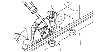
11. Rotate the manual shaft to the N position.
12. Set the adjustable wrench as shown in the figure to hold the manual shaft lever.
ar8uuw00000302
|
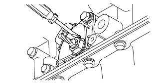
13. Remove the manual shaft nut.
14. Remove the washer and manual shaft lever component.
ar8uuw00000303
|
15. Pry off the lock washer using a flathead screwdriver.
ar8uuw00000304
|
16. Remove the nut and lock washer.
ar8uuw00000305
|
17. Remove the TR switch.
e5u513zw5036
|
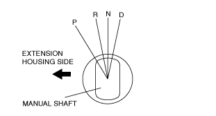
18. Rotate the manual shaft to the extension housing side fully and return two notches to set the N position.
chu0513w014
|
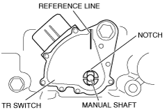
19. Install the TR switch and hand-tighten the new mounting bolts.
20. Verify the TR switch reference line and the notch of the manual shaft are aligned.
e5u513zw5081
|
21. Install the lock washer with the nut.
ar8uuw00000305
|
22. Stake the lock washer using a flathead screwdriver.
ar8uuw00000306
|
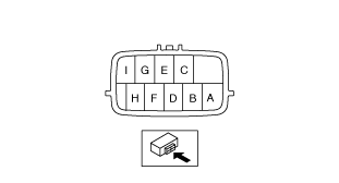
23. Tighten the TR switch mounting bolts.
24. Inspect for continuity between TR switch terminals E and H.
ar8uuw00000307
|
25. Install the manual shaft lever component and washer.
26. Set the adjustable wrench as shown in the figure to hold the manual shaft lever.
ar8uuw00000308
|
27. Tighten the manual shaft nut using a torque wrench.
28. Shift the selector lever to the P position.
29. Turn the manual shaft lever to the P position.
30. Inspect TR switch continuity. (See TRANSMISSION RANGE (TR) SWITCH INSPECTION [SJ6A-EL].)
31. Connect the TR switch connector.
32. Align the mark of the manual shaft lever component as shown in the figure.
ar8uuw00000300
|
33. Install the manual shaft lever component installation nut.
34. Install the insulator.
35. Install the catalytic converter. (See EXHAUST SYSTEM REMOVAL/INSTALLATION [13B-MSP].)
36. Install the rear tunnel member.
37. Install the front tunnel member.
38. Connect the negative battery cable.
39. Install the battery cover.
40. Install the engine cover. (See ENGINE COVER REMOVAL/INSTALLATION [13B-MSP].)
41. Inspect TR switch operation. (See TRANSMISSION RANGE (TR) SWITCH INSPECTION [SJ6A-EL].)