 |
ar8wzw00000239
STEERING WHEEL AND COLUMN REMOVAL/INSTALLATION
id061300281900
1. Remove the engine cover. (See ENGINE COVER REMOVAL/INSTALLATION [13B-MSP].)
2. For the L.H.D., remove the air cleaner and air cleaner insulator. (See INTAKE-AIR SYSTEM REMOVAL/INSTALLATION [13B-MSP].)
3. For the R.H.D., remove the following parts:
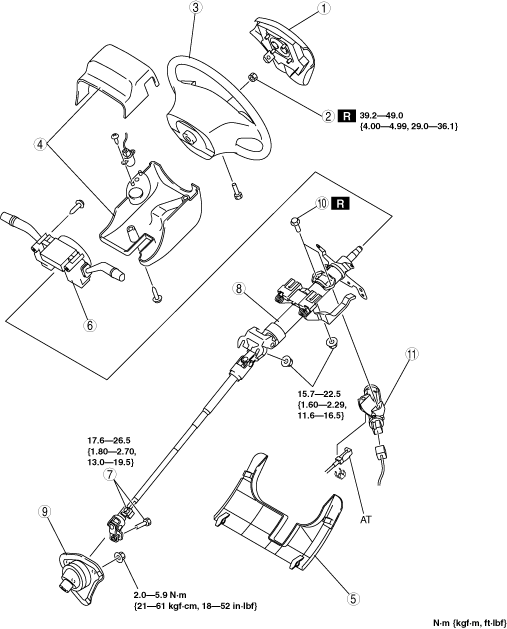
4. Remove in the order indicated in the table.
5. Install in the reverse order of removal.
6. If the steering lock component is replaced, perform programming for the immobilizer system related parts. (See IMMOBILIZER SYSTEM-RELATED PARTS PROGRAMMING [WITH KEYLESS ENTRY SYSTEM].)
7. After installation, set the EPS system to the neutral position. (See EPS SYSTEM NEUTRAL POSITION SETTING.)
ar8wzw00000239
|
|
1
|
Air bag module
|
|
2
|
Locknut
|
|
3
|
Steering wheel
(See Steering Wheel Removal Note.)
|
|
4
|
Column cover
|
|
5
|
Under cover
|
|
6
|
Clock spring, combination switch
|
|
7
|
Bolt (intermediate shaft)
|
|
8
|
Steering shaft
|
|
9
|
Dust cover
|
|
10
|
Steering lock mounting bolt
|
|
11
|
Steering lock
|
Steering Wheel Removal Note
1. Set the wheels in the straight-ahead position.
2. Remove the steering wheel using any commercially available puller.
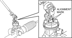
Bolt (Intermediate Shaft) Removal Note
1. Place alignment marks on the intermediate shaft joint, and the steering gear and linkage for proper installation.
ar8wzw00000240
|
2. Loosen the joint upper bolt.
3. Remove the joint lower bolt and detach the intermediate shaft from the steering gear.
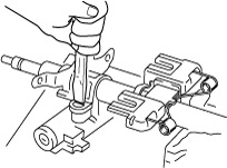
Steering Lock Mounting Bolt Removal Note
1. Make a groove in the heads of the steering lock mounting bolts using a chisel and hammer.
ar8wzw00000241
|
2. Remove the bolts using a flathead screwdriver.
3. Remove the steering lock.
Steering Lock Mounting Bolt Installation Note
1. Assemble the steering lock to the steering shaft.
2. Verify the operation condition of the steering lock system.
3. Install new steering lock mounting bolts.
4. Tighten the bolts until the heads break off.
ar8wzw00000242
|
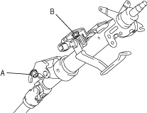
Steering Shaft Installation Note
1. Verify that the tilt lever is in the LOCK position.
2. Temporarily tighten nuts A and B as shown in the figure.
ar8wzw00000243
|
3. Tighten the nuts to the specified torque in the order of A, B.
Bolt (Intermediate Shaft) Installation Note
1. Align the marks made during removal and install the steering shaft to the steering gear.
ar8wzw00000240
|
2. Tighten the joint bolts (lower and upper).
3. After tightening the bolts, move the intermediate shaft joint up and down and verify that it is securely installed.
Steering Wheel Installation Note
1. Set the wheels in the straight-ahead position, and install the steering wheel.