|
1
|
INSPECT DRIVER-SIDE FRONT BUCKLE SWITCH CONNECTOR
• Turn the ignition switch to the LOCK position.
• Disconnect the negative battery cable and wait for 1 min or more.
• Inspect the driver-side front buckle switch connection. (Corrosion, damage, and disconnected pins)
• Is there any malfunction of the driver-side front buckle switch connector?
|
Yes
|
Replace the driver-side front buckle switch wiring harness.
|
|
No
|
Go to the next step.
|
|
2
|
INSPECT DRIVER-SIDE FRONT BUCKLE SWITCH
• Remove the driver-side front buckle.
• Inspect the driver-side front buckle switch.
• Is the driver-side front buckle switch normal?
|
Yes
|
Go to the next step.
|
|
No
|
Replace the driver-side front buckle.
|
|
3
|
INSPECT WIRING HARNESS BETWEEN DRIVER-SIDE BUCKLE SWITCH AND GROUND
• Inspect the wiring harness between driver-side front buckle switch terminal F and ground for the following:
-
― Short to power supply
― Open circuit
• Is the wiring harness normal?
|
Yes
|
Go to the next step.
|
|
No
|
Replace the wiring harness.
|
|
4
|
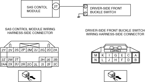
INSPECT WIRING HARNESS BETWEEN SAS CONTROL MODULE AND DRIVER-SIDE FRONT BUCKLE SWITCH
• Disconnect all SAS control module connectors.
• Inspect the wiring harness between SAS control module terminal 2T and driver-side front buckle switch terminal E for the following:
-
― Short to body ground
― Open circuit
-
Note
-
• Inspect for continuity while shaking the wiring harness between the SAS control module and driver-side front buckle switch.
• Is the wiring harness normal?
|
Yes
|
Go to the next step.
|
|
No
|
Replace the wiring harness between the SAS control module and the driver-side front buckle.
|
|
5
|
INSPECT THE WIRING HARNESS BETWEEN THE SAS CONTROL MODULE AND DRIVER-SIDE FRONT BUCKLE SWITCH FOR A SHORT CIRCUIT TO THE POWER SUPPLY
• Connect the negative battery cable.
• Turn the ignition switch to the ON position.
• Measure the voltage of SAS control module connector terminals 2T.
-
Note
-
• Measure the voltage while shaking the wiring harness between the SAS control module and driver-side front buckle switch.
• Is the voltage measured?
|
Yes
|
Replace the wiring harness between the SAS control module and the driver-side front buckle.
|
|
No
|
Go to the next step.
|
|
6
|
PERFORM DTC INSPECTION
• Disconnect the negative battery cable and wait for 1 min or more.
• Connect the driver-side front buckle switch connector.
• Connect the SAS control module connectors.
• Connect the negative battery cable.
• Clear DTCs using the M-MDS.
• Verify DTCs using the M-MDS.
• Are DTCs B2434, B2435 and/or B2691 displayed?
|
Yes
|
Replace the SAS control module.
|
|
No
|
DTC troubleshooting completed.
|