 |
ar8uuw00000682
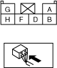
PANEL LIGHT CONTROL SWITCH INSPECTION
id091800806400
1. Connect the panel light control switch connector.
2. Connect the negative battery cable.
3. Measure the voltage at each terminal.
4. Disconnect the panel light control switch connector.
Terminal Voltage Table (Reference)
ar8uuw00000682
|
|
Terminal |
Signal name |
Connected to |
Measured condition |
Measured condition |
Voltage (V)/Continuity |
Inspection item(s) |
|---|---|---|---|---|---|---|
|
A
|
Illumination
|
Instrument cluster
|
Inspect using an oscilloscope. (See Terminals A and F Inspection.)
|
–
|
• Instrument cluster
• Each illumination
• Related wiring harnesses
|
|
|
F
|
Each illumination
|
|||||
|
B
|
TNS
|
TNS relay
|
Turn the light switch to the TNS or ON position.
|
B+
|
• TNS relay
(See RELAY INSPECTION.)
• ILLUMI 10 A fuse
• Related wiring harnesses
|
|
|
Turn the light switch to the OFF position.
|
1.0 or less
|
|||||
|
D
|
GND
|
Body ground
|
Under any condition
|
1.0 or less
|
• GND
• Related wiring harnesses
|
|
|
G
|
IG1
|
Ignition switch
|
Turn the ignition switch to the ON position.
|
B+
|
• Ignition switch
(See IGNITION SWITCH INSPECTION.)
• Related wiring harnesses
|
|
|
Turn the ignition switch to the ACC or LOCK position.
|
1.0 or less
|
|||||
|
H
|
Dimmer cancel
|
Instrument cluster/center panel module
|
Turn the light switch to the TNS or ON position.
|
Dimmer cancel switch is on.
|
B+
|
• Instrument cluster
• Center panel module
• Related wiring harnesses
|
|
Dimmer cancel switch is off.
|
1.0 or less
|
|||||
Terminals A and F Inspection
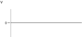
1. Measure the wave pattern of panel light control switch terminals A and F using an oscilloscope.
ar8uuw00000683
|
2. Turn the light switch to the TNS or ON position.
3. Turn the panel light control switch to the brightest setting.
4. Verify that the wave pattern is as shown in the figure.
ar8uuw00000684
|
5. Turn the panel light control switch to the darkest position and verify that the wave pattern is as shown in the figure.
chu0918w169
|