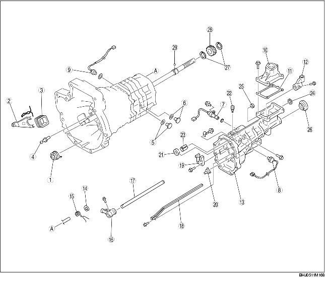
EXTENSION HOUSING COMPONENT DISASSEMBLY
BHE051117010102
1. Disassemble in the order indicated in the table.
BP
|
1
|
Clutch release bearing
|
|
2
|
Clutch release fork
|
|
3
|
Dust cover
|
|
4
|
Pivot pin
|
|
5
|
Filler plug, gasket
|
|
6
|
Drain plug, gasket
|
|
7
|
Speedometer sensor
|
|
8
|
Neutral switch
|
|
9
|
Buck-up light switch
|
|
10
|
Control case
|
|
11
|
Gasket
|
|
12
|
Control rod end
|
|
13
|
Extension housing component
|
|
14
|
Retaining ring
|
|
15
|
Torsion spring
|
|
16
|
Control lever
|
|
17
|
Control rod
|
|
18
|
Oil passage
|
|
19
|
Stopper block
|
|
20
|
Oil funnel
|
|
21
|
Lever support
|
|
22
|
Breather
|
|
23
|
Baffle plate
|
|
24
|
Plug
|
|
25
|
Bushing
|
|
26
|
Oil seal
|
|
27
|
Snap ring
|
|
28
|
Speedometer drive gear
|
|
29
|
Steel ball
|
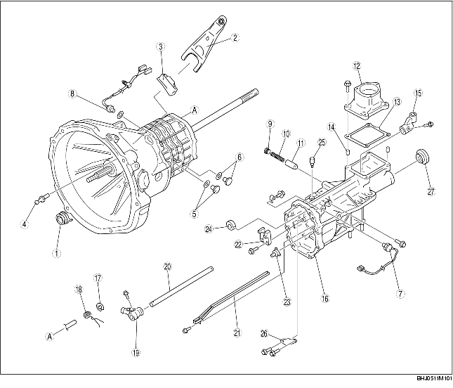
13B-MSP
|
1
|
Clutch release collar
|
|
2
|
Clutch release fork
|
|
3
|
Dust cover
|
|
4
|
Pivot pin
|
|
5
|
Filler plug, gasket
|
|
6
|
Drain plug, gasket
|
|
7
|
Neutral switch
|
|
8
|
Back-up light switch
|
|
9
|
Plug
|
|
10
|
Pressure spring
|
|
11
|
Push pin component
|
|
12
|
Control case
|
|
13
|
Gasket
|
|
14
|
Tubular pin
|
|
15
|
Control rod end
|
|
16
|
Extension housing component
|
|
17
|
Retaining ring
|
|
18
|
Torsion spring
|
|
19
|
Control lever
|
|
20
|
Control rod
|
|
21
|
Oil passage
|
|
22
|
Stopper block
|
|
23
|
Oil funnel
|
|
24
|
Lever support
|
|
25
|
Breather
|
|
26
|
Baffle plate
|
|
27
|
Oil seal
|
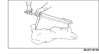
Plug Disassembly Note (BP)
-
Note
-
• Use a rag to prevent damage to the extension housing.
1. Remove the plug using a suitable bar and a hammer.
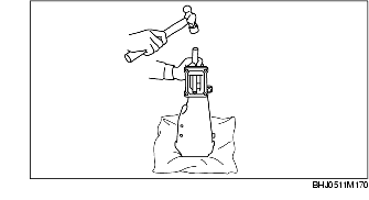
Bushing Disassembly Note (BP)
-
Note
-
• Use a rag to prevent damage to the extension housing.
1. Remove the bushing using a suitable bar and a hammer.