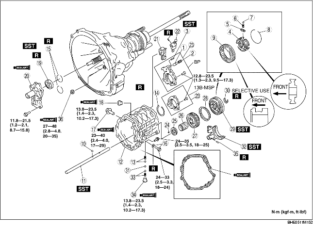
1. Assemble in the order indicated in the table.
2. Verify the following after assembly.
|
1
|
Push pin
|
|
2
|
Pressure spring
|
|
3
|
Spring pin
|
|
4
|
Clutch hub
|
|
5
|
Synchronizer key
|
|
6
|
Synchronizer key spring
|
|
7
|
Steel ball
|
|
8
|
Retaining ring
|
|
9
|
Clutch hub sleeve
|
|
10
|
Steel ball
|
|
11
|
Shift rod
(See Shift Rod Assembly Note.)
|
|
12
|
Transmission case
|
|
13
|
Pressure spring, steel ball
|
|
14
|
Snap ring (rear)
|
|
15
|
Snap ring (front)
|
|
16
|
Bolt and gasket
|
|
17
|
Bolt
|
|
18
|
Plug
|
|
19
|
Oil seal
(See Oil Seal Assembly Note.)
|
|
20
|
Front cover
|
|
21
|
Interlock sleeve
|
|
22
|
Inner shift lever
|
|
23
|
Bearing cover component
|
|
24
|
Pin
|
|
25
|
Thrust washer
|
|
26
|
Needle bearing
|
|
27
|
6th gear
|
|
28
|
Synchronizer ring
|
|
29
|
Clutch hub component (6th)
|
|
30
|
Snap ring
(See Snap Ring Assembly Note.)
|
|
31
|
Steel ball
|
|
32
|
6th shift fork
(See 6th Shift Fork Assembly Note.)
|
|
33
|
Steel ball, pressure spring
|
|
34
|
Plug
|
|
35
|
Spring pin
|
|
36
|
Plug
(See Plug Assembly Note.)
|
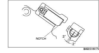
1. Install the push pin so that its notch faces in the direction shown in the figure.
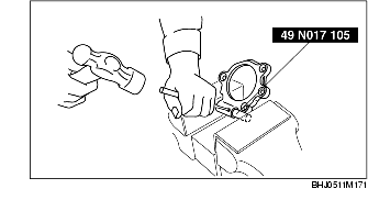
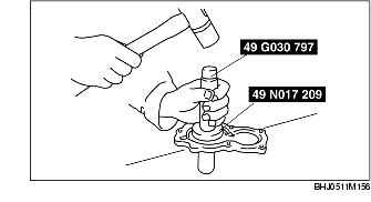
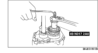
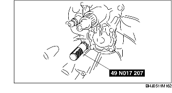
1. Secure the bearing cover component compressing the pressure spring using the SST.
2. Drive the spring pin.
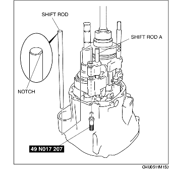
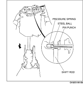
1. Install the SST into the clutch housing.
2. Install the steel ball into the shift arm (5th).
3. Taking care so that the steel ball does not drop out, carefully insert the shift rod until it contacts the SST installed to the clutch housing.
4. Turn the notch of the shift rod end toward the shift rod A.
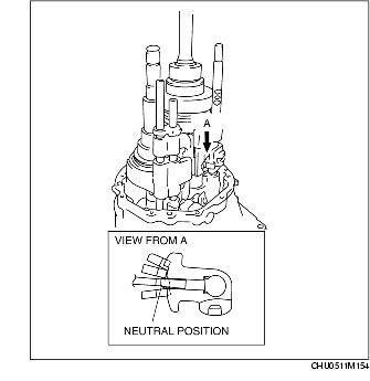
1. Set the shift operation system to the neutral position.
2. Install the pressure spring and steel ball into the transmission case, then install the transmission case onto the clutch housing pressing with a pin punch so that the steel ball does not spring out.
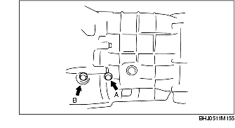
1. Tighten the transmission case mounting bolt, then tighten the new gasket and bolt A (for the reverse idler shaft).
2. Tighten bolt B tightened temporarily on the clutch housing.
1. Install the new oil seal in the front cover using the SSTs and a hammer.
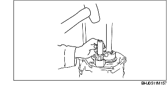
1. Install the inner shift lever using a suitable pipe and a hammer.
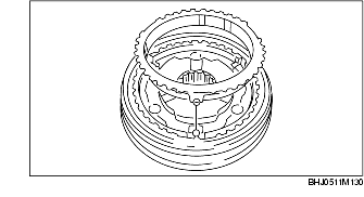
1. Securely align the tab on the synchronizer ring with the key groove of the clutch hub.
2. Carefully install the clutch hub component (6th) using the SST.
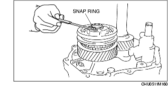
1. Install the snap ring removed during disassembly, and measure the clearance between the snap ring and the installation groove using a feeler gauge.
2. Select the new snap ring from the following table so that the clearance measured in Step 1 is within specification, and install it in the countershaft gear.
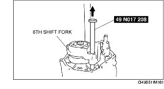
1. Install the 6th shift fork in the clutch hub component.
2. Insert the steel ball from the transmission case.
3. Pass the SST through the 6th shift fork and install in the shift rod.
4. Pull the SST up, then install the steel ball, pressure spring and plug from outside of the transmission case and secure the shift rod.
1. Remove the SST installed to the clutch housing, and install the plug.