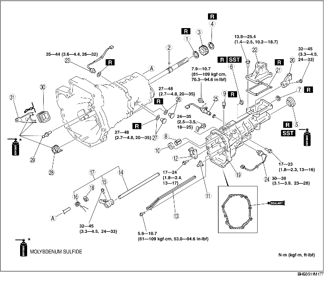
1. Assemble in the order indicated in the table.
BP
|
1
|
Snap ring
|
|
2
|
Steel ball
|
|
3
|
Speedometer drive gear
|
|
4
|
Snap ring
|
|
5
|
Oil seal
(See Oil Seal Assembly Note.)
|
|
6
|
Bushing
|
|
7
|
Plug
(See Plug Assembly Note (BP))
|
|
8
|
Baffle plate
|
|
9
|
Breather
|
|
10
|
Lever support
|
|
11
|
Oil funnel
|
|
12
|
Stopper block
|
|
13
|
Oil passage
|
|
14
|
Control rod
|
|
15
|
Control lever
|
|
16
|
Torsion spring
(See Torsion Spring Assembly Note.)
|
|
17
|
Control rod and control lever component
|
|
18
|
Retaining ring
|
|
19
|
Extension housing component
|
|
20
|
Control rod end
|
|
21
|
Gasket
|
|
22
|
Control case
|
|
23
|
Back-up light switch
|
|
24
|
Neutral switch
|
|
25
|
Speedometer sensor
|
|
26
|
Drain plug, gasket
|
|
27
|
Filler plug, gasket
|
|
28
|
Clutch release collar
|
|
29
|
Pivot pin
|
|
30
|
Dust cover
|
|
31
|
Clutch release fork
|
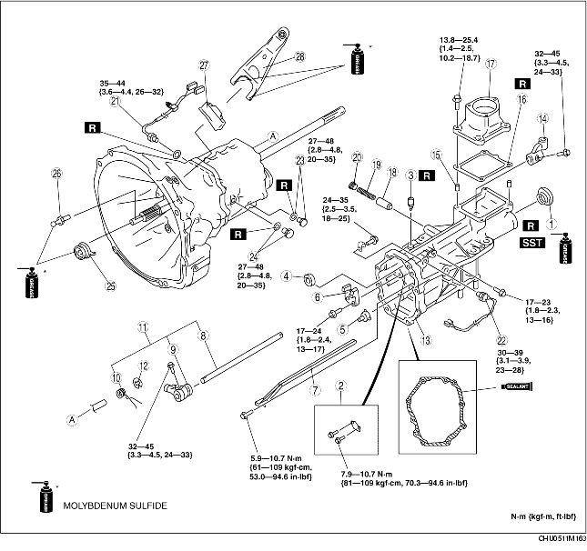
13B-MSP
|
1
|
Oil seal
(See Oil Seal Assembly Note.)
|
|
2
|
Baffle plate
|
|
3
|
Breather
|
|
4
|
Lever support
|
|
5
|
Oil funnel
|
|
6
|
Stopper block
|
|
7
|
Oil passage
|
|
8
|
Control rod
|
|
9
|
Control lever
|
|
10
|
Torsion spring
(See Torsion Spring Assembly Note.)
|
|
11
|
Control rod and control lever component
|
|
12
|
Retaining ring
|
|
13
|
Extension housing component
|
|
14
|
Control rod end
|
|
15
|
Tubular pin
|
|
16
|
Gasket
|
|
17
|
Control case
|
|
18
|
Push pin component
|
|
19
|
Pressure spring
|
|
20
|
Plug
|
|
21
|
Back-up light switch
|
|
22
|
Neutral switch
|
|
23
|
Drain plug, gasket
|
|
24
|
Filler plug, gasket
|
|
25
|
Clutch release collar
|
|
26
|
Pivot pin
|
|
27
|
Dust cover
|
|
28
|
Clutch release fork
|
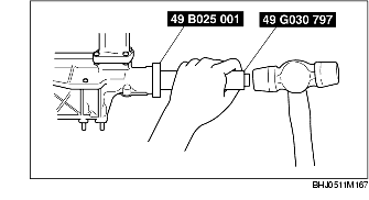
1. Install a new oil seal in the extension housing using the SSTs and a hammer.
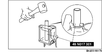
1. Install the new bushing in the extension housing using the SST and a hammer.
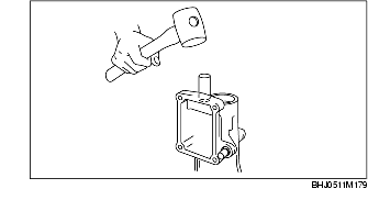
1. Install the new plug in the extension housing using a suitable round bar and a hammer.
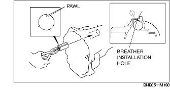
1. Grip the pawl of the baffle plate and shrink the outside diameter using a plier.
2. Face the baffle plate in the direction shown in the figure and insert until it contacts the depth of the baffle plate installation hole.
1. Install the torsion spring to the shift lever as shown in the figure.