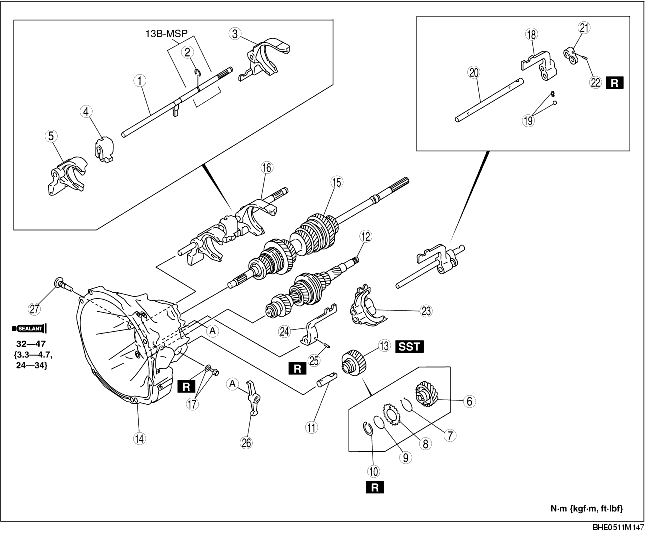
1. Assemble in the order indicated in the table.
|
1
|
Shift rod
|
|
2
|
Snap ring
|
|
3
|
1st/2nd shift fork
|
|
4
|
Interlock sleeve
|
|
5
|
5th/reverse shift fork
|
|
6
|
Reverse idler gear
|
|
7
|
Torsion spring
|
|
8
|
Friction gear
|
|
9
|
Spacer
|
|
10
|
Snap ring
|
|
11
|
Reverse idler shaft
|
|
12
|
Countershaft component
|
|
13
|
Reverse idler gear component
|
|
14
|
Clutch housing
(See Clutch Housing Assembly Note.)
|
|
15
|
Main drive gear and mainshaft component
|
|
16
|
Shift fork and shift rod component (mainshaft)
|
|
17
|
Bolt and gasket
|
|
18
|
Shift arm (5th)
|
|
19
|
Pressure spring, steel ball
|
|
20
|
Shift rod
|
|
21
|
Stopper block
|
|
22
|
Spring pin
|
|
23
|
3rd/4th shift fork
|
|
24
|
Shift arm (reverse)
|
|
25
|
Spring pin
|
|
26
|
5th/reverse counter lever
|
|
27
|
Crank lever shaft
|
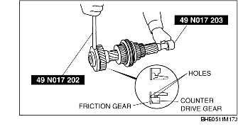
1. Turn the friction gear clockwise using the SSTs (49 N017 202, 49 N017 203), and align the counter drive gear hole with the friction gear hole.
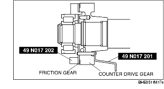
2. Insert the SST (49 N017 201) through the holes from the counter drive gear side, and secure the friction gear.
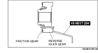
1. Turn the friction gear counterclockwise by hand, and align the reverse idler gear hole with the friction gear.
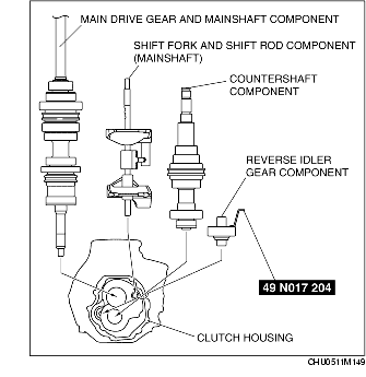
2. Insert the SST (49 N017 204) through the holes from the reverse idler gear side, and secure the friction gear.
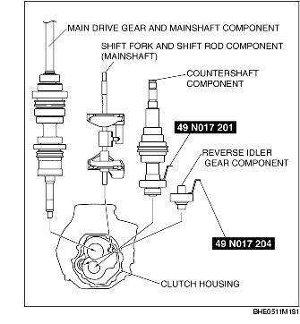
1. Install the countershaft component and the reverse idler gear component installed with the SSTs and the main drive gear and mainshaft component, shift fork and shift rod component (mainshaft) onto the clutch housing together.
BP
13B-MSP
2. Remove the SSTs installed to the countershaft component and the reverse idler gear component after installing.
1. Install a new gasket and bolt into the clutch housing and tighten temporarily.
2. Fully tighten the new gasket and bolt after installing the transmission case.
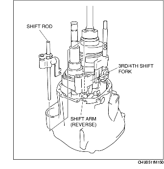
1. Temporarily install the 3rd/4th shift fork and shift arm (reverse) into the clutch housing.
2. Pass the shift rod through the 3rd/4th shift fork and shift arm (reverse).
3. Tap a new spring pin into the shift arm (reverse) head.
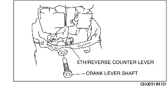
1. Install the 5th/reverse counter lever as shown in the figure, and secure it with the crank lever shaft.