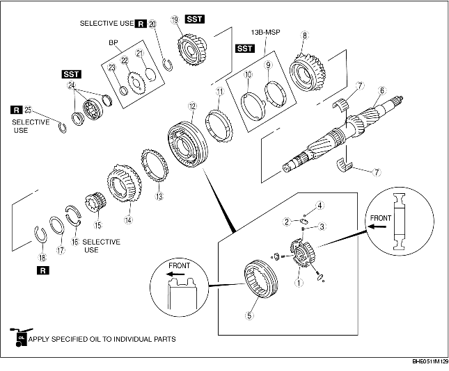
1. Assemble in the order indicated in the table.
2. Verify the following after assembly.
|
1
|
Clutch hub
|
|
2
|
Synchronizer key
|
|
3
|
Synchronizer key spring
|
|
4
|
Steel ball
|
|
5
|
Clutch hub sleeve
|
|
6
|
Countershaft gear
|
|
7
|
Needle bearing
|
|
8
|
Counter 3rd gear
|
|
9
|
Inner ring
|
|
10
|
Middle ring
|
|
11
|
Synchronizer ring
|
|
12
|
Clutch hub component (3rd/4th)
|
|
13
|
Synchronizer ring
|
|
14
|
Counter 4th gear
|
|
15
|
Inner race
|
|
16
|
Thrust washer
(See Thrust Washer Assembly Note.)
|
|
17
|
Retaining ring
|
|
18
|
Snap ring
|
|
19
|
Counter drive gear
|
|
20
|
Snap ring (friction gear)
|
|
21
|
Torsion spring
|
|
22
|
Friction gear
|
|
23
|
Snap ring
|
|
24
|
Roller bearing
(See Roller Bearing Assembly Note.)
|
|
25
|
Snap ring (roller bearing)
|
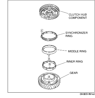
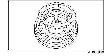
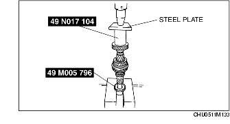
1. Securely align the tabs on each ring of the 3rd gear side with the installation hole of the 3rd gear and the key groove of the clutch hub.
2. Securely align the tab on the synchronizer ring of 4th gear side with the key groove of the clutch hub.
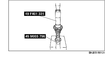
3. Carefully install the clutch hub component (3rd/4th) using the SSTs and a press.
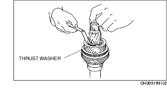
1. Install the thrust washer removed during disassembly, and measure the clearance between the thrust washer and the installation groove using a feeler gauge.
2. Select the new thrust washer from the following table so that the clearance measured in Step 1 is within specification, and install it in the countershaft gear with the identification mark facing up.
Thrust washer size
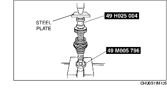
mm {in}1. Install the counter drive gear using the SSTs.
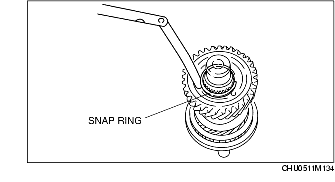
1. Install the snap ring removed during disassembly, and measure the clearance between the snap ring and the installation groove using a feeler gauge.
2. Select the new snap ring from the following table so that the clearance measured in Step 1 is within specification, and install it in the countershaft gear.
Snap ring size
mm {in}1. Install the roller bearing using the SSTs.
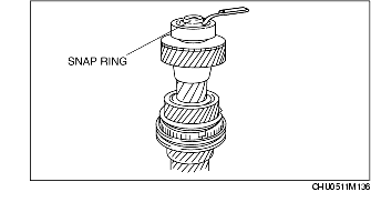
1. Install the snap ring removed during disassembly, and measure the clearance between the snap ring and the installation groove using a feeler gauge.
2. Select the new snap ring from the following table so that the clearance measured in Step 1 is within specification, and install it in the countershaft gear.
Snap ring size
mm {in}