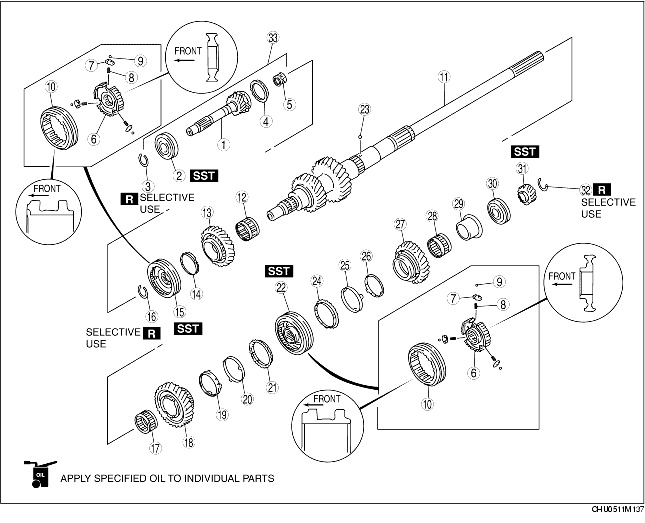
1. Assemble in the order indicated in the table.
2. Verify the following after assembly.
|
1
|
Main drive gear
|
|
2
|
Bearing
(See Bearing Assembly Note.)
|
|
3
|
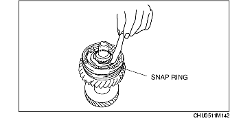
Snap ring (bearing)
|
|
4
|
Synchronizer ring
|
|
5
|
Needle bearing
|
|
6
|
Clutch hub
|
|
7
|
Synchronizer key
|
|
8
|
Synchronizer key spring
|
|
9
|
Steel ball
|
|
10
|
Clutch hub sleeve
|
|
11
|
Mainshaft
|
|
12
|
Needle bearing
|
|
13
|
Reverse gear
|
|
14
|
Synchronizer ring
|
|
15
|
Clutch hub component (5th/reverse)
|
|
16
|
Snap ring (reverse gear)
|
|
17
|
Needle bearing
|
|
18
|
2rd gear
|
|
19
|
Inner ring
|
|
20
|
Middle ring
|
|
21
|
Synchronizer ring
|
|
22
|
Clutch hub component (1st/2nd)
|
|
23
|
Steel ball
|
|
24
|
Synchronizer ring
|
|
25
|
Middle ring
|
|
26
|
Inner ring
|
|
27
|
1st gear
|
|
28
|
Needle bearing
|
|
29
|
Inner race
|
|
30
|
Bearing
|
|
31
|
6th gear
(See 6th Gear Assembly Note.)
|
|
32
|
Snap ring (6th gear)
|
|
33
|
Main drive gear component
|
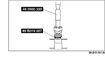
1. Install the bearing using the SSTs.
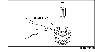
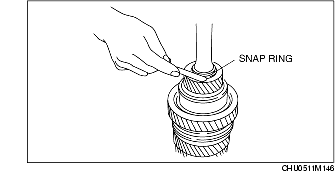
1. Install the snap ring removed during disassembly, and measure the clearance between the snap ring and the installation groove using a feeler gauge.
2. Select the new snap ring from the following table so that the clearance measured in Step 1 is within specification, and install it in the main drive gear.
Snap Ring size
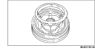
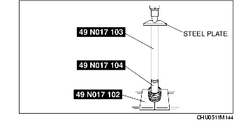
mm {in}1. Securely align the tab on the synchronizer ring with the key groove of the clutch hub.
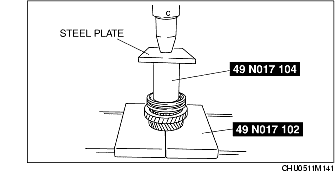
2. Carefully install the clutch hub component (5th/reverse) using the SSTs and a press.
1. Install the snap ring removed during disassembly, and measure the clearance between the snap ring and the installation groove using a feeler gauge.
2. Select the new snap ring from the following table so that the clearance measured in Step 1 is within specification, and install it in the mainshaft.
Snap Ring size
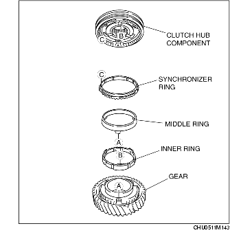
mm {in}1. Securely align the tab on each ring with the installation hole of the 2nd gear and the key groove of the clutch hub.
2. Carefully install the clutch hub component (1st/2nd) using the SSTs and a press.
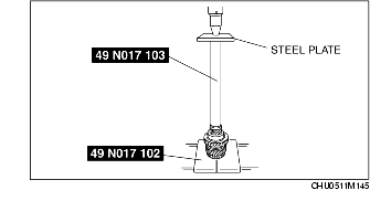
1. Install the bearing and 6th gear using the SSTs and a press.
1. Install the snap ring removed during disassembly, and measure the clearance between the snap ring and the installation groove using a feeler gauge.
2. Select the new snap ring from the following table so that the clearance measured in Step 1 is within specification, and install it in the mainshaft.
Snap Ring size
mm {in}