1. Disassemble the transmission in a clean area (dust-proof work space) to prevent entry of dust into the mechanisms.
2. Inspect the individual transmission components in accordance with the QUICK DIAGNOSIS CHART during disassembly.
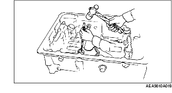
3. Use only plastic hammers when applying force to separate the light alloy case joints.
4. Never use rags during disassembly; they may leave particles that can clog fluid passages.
5. Because several parts resemble one another, arrange them so that they do not get mixed up.
6. Disassemble the control valve component and thoroughly clean it when the clutch or brake band has burned or when the ATF has degenerated.
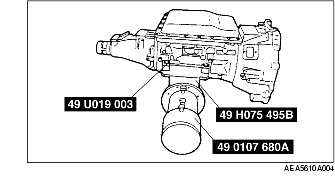
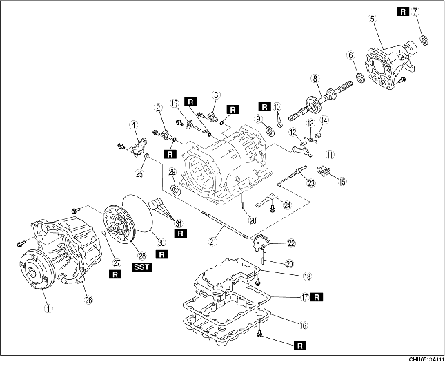
1. Remove the torque converter, and immediately turn it so that the hole faces upward. This will help to keep any remaining fluid from spilling.
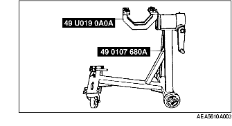
2. Assemble the SSTs.
3. Mount the transmission on the SSTs.
4. Turn down the oil pan in order to gather any material.
5. Remove the oil pan and the gasket.
6. Examine any material found in the oil pan or on the magnet to determine the condition of the transmission.
|
Material
|
Cause
|
|---|---|
|
Clutch facing material
|
Drive plate wear
|
|
Steel (magnetic)
|
Bearing, gear, and driven plate wear
|
|
Aluminium (non magnetic)
|
Aluminium part wear
|
7. Install the oil pan with a few bolts to protect the control valve body.
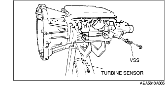
8. Remove the turbine sensor and the vehicle speed sensor (VSS).
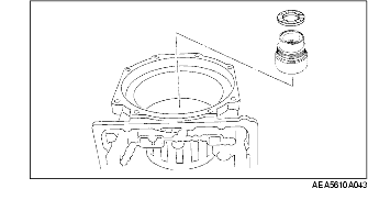
9. Remove the O-ring from the turbine sensor and the VSS.
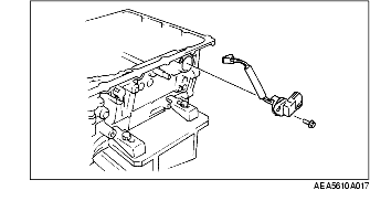
10. Remove the TR switch.
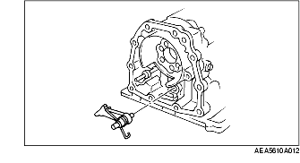
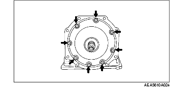
11. Remove the extension housing as shown in the figure.
12. Remove the bearing from the extension housing.
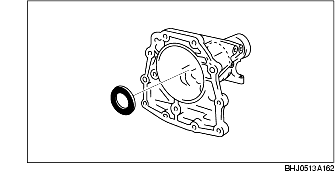
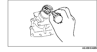
13. Remove the oil seal from the extension housing using a screwdriver.
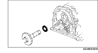
14. Remove the output shaft component and the bearing.
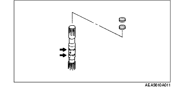
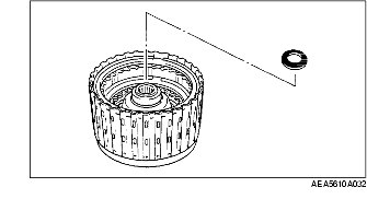
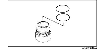
15. Remove the seal rings from the output shaft component.
16. Remove the parking pawl, shaft, spring, and the spacer.
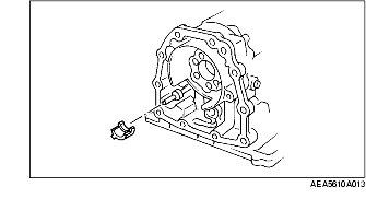
17. Remove the actuator support.
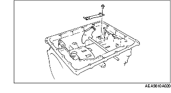
18. Remove the oil pan.
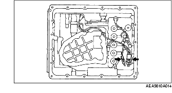
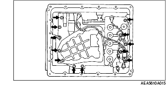
19. Disconnect the harness component as shown in the figure.
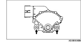
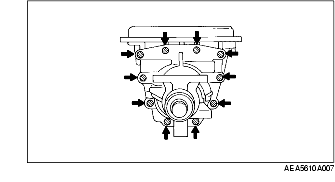
20. Remove the bolts as shown in the figure.
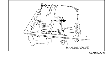
21. Remove the control valve body.
22. Remove the harness component.
23. Remove the O-ring from the harness component.
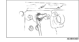
24. Remove the roll pin using a pin punch.
25. Remove the roll pin.
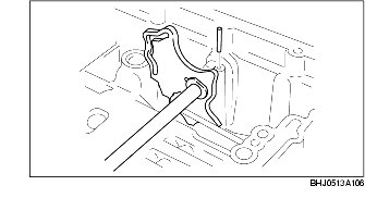
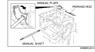
26. Remove the manual shaft, manual plate and parking rod.
27. Remove the detent spring.
28. Remove the oil seal using a screwdriver.
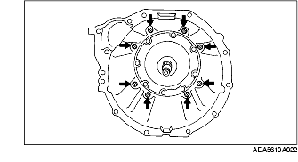
29. Remove the torque converter housing as shown in the figure.
30. Remove the O-ring from the input shaft.
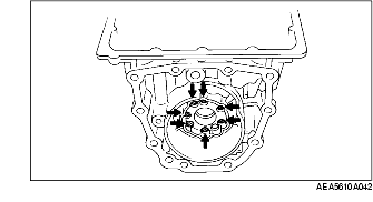
31. Remove the bolts as shown in the figure.
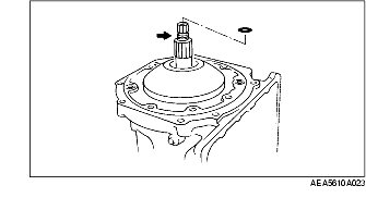
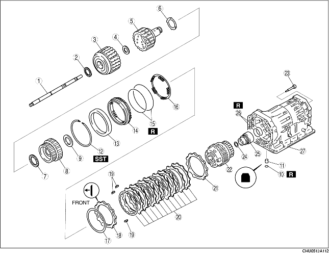
32. Install the SST to the oil pump.
33. While pulling the oil pump shaft upward, remove the oil pump by sliding the weight of the SST.
34. Remove the SST from the oil pump.
35. Remove any old sealant from the oil pump.
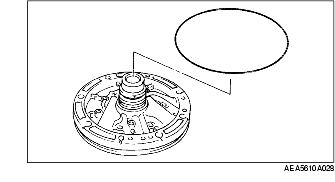
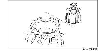
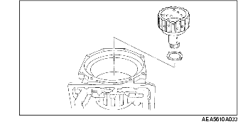
36. Remove the bearing from the oil pump.
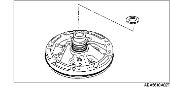
37. Remove the O-ring from the oil pump.
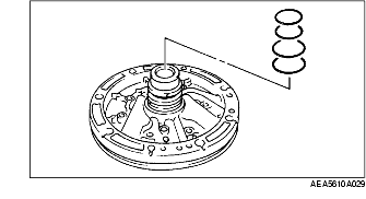
38. Remove the seal rings from the oil pump.
39. Remove the input shaft.
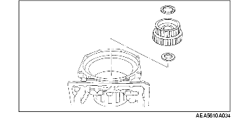
40. Remove the bearing and the reverse and high clutch drum.
41. Remove the bearing from the reverse and high clutch drum.
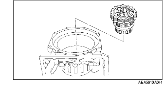
42. Remove the high clutch hub and the bearing race.
43. Remove the bearing, front sun gear, and the bearing race.
44. Inspect the 2-4 brake operation. (See 2-4 BRAKE PREINSPECTION.)
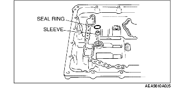
45. Remove the seal ring and the sleeve.
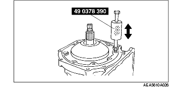
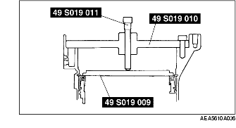
46. Install the SSTs to the transmission case.
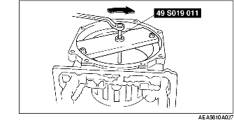
47. Compress the 2-4 brake retainer using the SST.
48. Remove the snap ring.
49. Remove the SSTs.
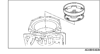
50. Remove the 2-4 brake retainer and the return spring.
51. Remove the 2-4 brake piston from the 2-4 brake retainer.
52. Remove the seal rings from the 2-4 brake piston.
53. Remove the carrier component, plates of the 2-4 brake, and the N-spring.
54. Remove the bolts.
55. Remove the bearing and the low one-way clutch inner race.
56. Remove the seal rings from the low one-way clutch inner race.