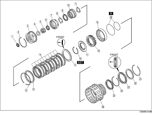
1. Disassemble in the order indicated in the table.
|
1
|
Bearing
|
|
2
|
Snap ring
|
|
3
|
Front carrier
|
|
4
|
Bearing
|
|
5
|
Rear sun gear
|
|
6
|
Bearing
|
|
7
|
Rear carrier
|
|
8
|
Bearing race
|
|
9
|
Bearing
|
|
10
|
Internal gear
|
|
11
|
Bearing race
|
|
12
|
Snap ring
|
|
13
|
Retaining plate
|
|
14
|
Drive and driven plate
|
|
15
|
Dished plate
|
|
16
|
Snap ring
(See Snap Ring Disassembly Note.)
|
|
17
|
Cancel cover
|
|
18
|
Return spring
|
|
19
|
Low clutch piston
|
|
20
|
Seal ring
|
|
21
|
Snap ring
|
|
22
|
Side plate
|
|
23
|
Low one-way clutch
|
|
24
|
Snap ring
|
|
25
|
Bearing
|
|
26
|
Low clutch drum
|
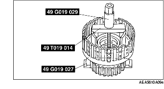
1. Install the SSTs in the clutch drum as shown.
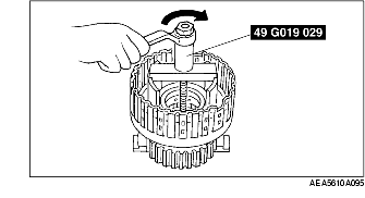
2. Compress the cancel cover using the SST.
3. Remove the snap ring.
4. Remove the SSTs.
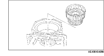
1. Install the low one-way clutch inner race to the transmission case.
2. Install the low clutch drum to the transmission case correctly.
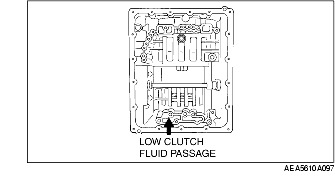
3. Apply compressed air to the part indicated in the figure and remove the low clutch piston.