HEATED OXYGEN SENSOR (HO2S) INSPECTION
id014000802300
-
Note
-
• Before performing the following inspection, make sure to follow the troubleshooting flowchart. (See Troubleshooting Procedure.)
HO2S Voltage Inspection
1. Warm up the engine to normal operating temperature.
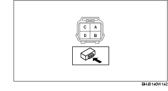
2. Disconnect the HO2S connector.
3. Connect the positive probe of the tester (digital type) to HO2S terminal A, and the negative probe to HO2S terminal B and measure the voltage.
4. Maintain the engine speed at 3,000 rpm until the voltage indicates approx. 0.5-0.7 V.
5. Verify that the voltage is as indicated in the table when the engine is raced repeatedly.
-
• If it cannot be verified, replace the HO2S. (See HEATED OXYGEN SENSOR (HO2S) REMOVAL/INSTALLATION.)
HO2S Voltage Inspection
|
Engine condition
|
Voltage (V)
|
|
Accelerated
|
0.5-1.0
|
|
Decelerated
|
0-0.5
|
HO2S Heater Resistance Inspection
1. Disconnect the HO2S connector.
2. Measure the resistance between HO2S terminals C and D.
-
• If not within the specification, replace the HO2S. (See HEATED OXYGEN SENSOR (HO2S) REMOVAL/INSTALLATION.)
HO2S heater resistance
-
14.1-18.9 ohms [20 °C {68 °F}]
Circuit Open/Short Inspection
1. Disconnect the PCM connector.
2. Disconnect the HO2S connector.
3. Inspect the following wiring harnesses for open or short circuit. (Continuity inspection)
Open circuit
-
• If there is no continuity in the following wiring harnesses, there is an open circuit. Repair or replace the wiring harness.
-
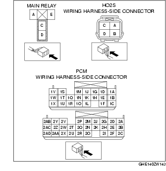
- HO2S terminal A and PCM terminal 2Q
-
- HO2S terminal B and PCM terminal 1U
-
- HO2S terminal C and main relay terminal C
-
- HO2S terminal D and PCM terminal 2A
Short circuit
-
• If there is continuity in the following wiring harnesses, there is a short circuit. Repair or replace the wiring harness.
-
- HO2S terminal A and body ground
-
- HO2S terminal A and power supply
-
- HO2S terminal B and body ground
-
- HO2S terminal B and power supply
-
- HO2S terminal D and body ground