 |
ar8wzw00001524
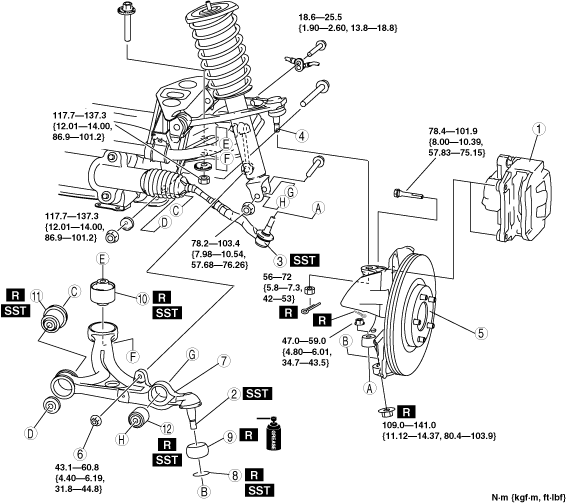
FRONT LOWER ARM REMOVAL/INSTALLATION
id021300800600
1. Remove in the order indicated in the table.
2. Install in the reverse order of removal.
3. Inspect the front wheel alignment. (See FRONT WHEEL ALIGNMENT.)
ar8wzw00001524
|
|
1
|
Caliper and mounting support
|
|
2
|
Front lower arm ball joint
|
|
3
|
Tie-rod end
|
|
4
|
Front upper arm ball joint
|
|
5
|
Front hub, steering knuckle component
|
|
6
|
Stabilizer control link nut (front lower arm side)
|
|
7
|
Front lower arm
|
|
8
|
Clip
(See Clip Installation Note.)
|
|
9
|
Dust boot
|
|
10
|
Bushing (rear side)
|
|
11
|
Bushing (front side)
|
|
12
|
Bushing (shock absorber lower side connecting part)
|
Caliper and Mounting Support Removal Note
1. Remove the caliper and mounting support from the steering knuckle and suspend it with a cable in a location out of the way.
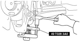
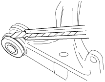
Front Lower Arm Ball Joint Removal Note
1. Disconnect the front lower arm ball joint from the steering knuckle using the SST.
ar8wzw00001502
|
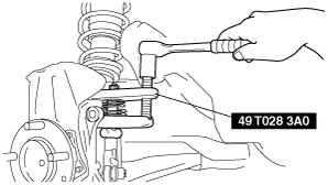
Upper Arm Ball Joint Removal Note
1. Loosen the bolts on the vehicle side.
2. Disconnect the upper arm ball joint using the SST.
ar8wzw00001503
|
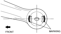
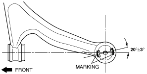
Bushing (Rear Side) Removal Note
1. Mark the front upper arm as shown in the figure.
ar8wzw00001504
|
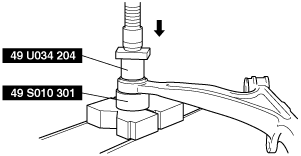
2. Remove the bushing using the SSTs.
ar8wzw00001505
|
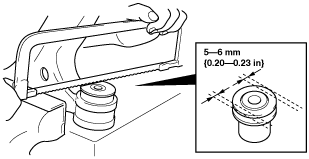
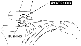
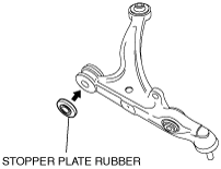
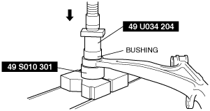
Bushing (Front Side) Removal Note
1. Cut off the stopper plate rubber using a razor.
ar8wzw00001506
|
2. Cut off 5—6 mm {0.20—0.23 in} from each side of the knob end of the bushing using a hacksaw.
chu0213w010
|
3. Remove the bushing using the SSTs.
e5u213zw5020
|
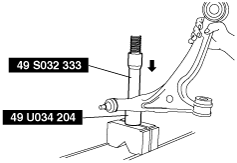
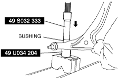
Bushing (Shock Absorber Lower Side Connecting Part) Removal Note
1. Remove the bushing using the SSTs.
ar8wzw00001507
|
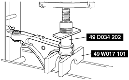
Bushing (Shock Absorber Lower Side Connecting Part) Installation Note
1. Compress the bushing using the SSTs.
chu0213w011
|
Bushing (Front Side) Installation Note
1. Press the bushing in using the SSTs.
chu0213w023
|
2. Insert the stopper plate rubber into the inner pipe of the bushing (front side).
chu0213w024
|
Bushing (Rear Side) Installation Note
1. Align the marks placed during removal and install the bushing.
ar8wzw00001508
|
2. Press the bushing in using the SSTs.
chu0213w014
|
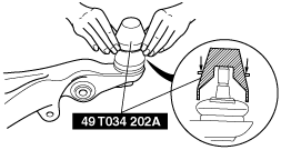
Clip Installation Note
1. Wipe the grease off the ball joint stud.
2. Fill the inside of the new dust boot with grease.
3. Install the dust boot to the ball joint.
4. Install the clip using the SST.
ar8wzw00001509
|
5. Verify that the clip is installed securely to the groove.
6. Wipe off any excess grease.
Front Lower Arm Installation Note
1. Install the front lower arm rear side bushing part horizontally.
2. Install the front lower arm front side bushing part.