Diagnostic procedure
|
STEP
|
INSPECTION
|
ACTION
|
|
|---|---|---|---|
|
1
|
INSPECT BRAKE PEDAL POSITION SIGNAL INPUT TO DSC HU/CM USING M-MDS
• Connect the M-MDS to the DLC-2.
• Select the "BOO_ABS" PID and verify that the display is switched as follows according to the brake pedal condition:
• Does the "BOO_ABS" PID change normally?
|
Yes
|
Go to Step 6.
|
|
No
|
Go to the next step.
|
||
|
2
|
INSPECT STOP LIGHT FUSE CONDITION
• Turn the ignition switch off.
• Inspect the STOP 15 A fuse.
• Is the STOP 15 A fuse normal?
|
Yes
|
Go to the next step.
|
|
No
|
Replace the fuse, then go to Step 11.
|
||
|
3
|
INSPECT BRAKE SWITCH
• Inspect the brake switch.
(See BRAKE SWITCH INSPECTION.)
• Is the brake switch normal?
|
Yes
|
Go to the next step.
|
|
No
|
Replace the brake switch, then go to Step 11.
|
||
|
4
|
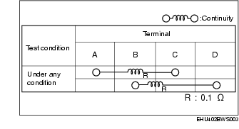
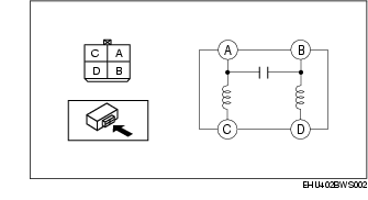
INSPECT BRAKE LIGHT NOISE FILTER
• Inspect the brake light noise filter.
• Is the brake light noise filter normal?
|
Yes
|
Go to the next step.
|
|
No
|
Replace the wiring harness (including the brake light noise filter), then go to Step 11.
|
||
|
5
|
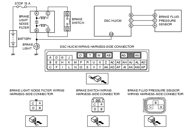
INSPECT FOR OPEN CIRCUIT IN WIRING HARNESS BETWEEN DSC HU/CM AND STOP LIGHT FUSE
• Disconnect the DSC HU/CM, brake switch, and brake light noise filter connectors.
• Inspect the vehicle wiring harness-side connectors for continuity between the following terminals:
• Is there continuity?
|
Yes
|
Go to the next step.
|
|
No
|
Repair or replace the wiring harness for open circuit between brake switch, brake light noise filter and DSC HU/CM, then go to Step 11.
|
||
|
6
|
INSPECT BRAKE FLUID PRESSURE SENSOR POWER SUPPLY FOR OPEN CIRCUIT
• Turn the ignition switch to the ON position (engine off).
• Measure the voltage between brake fluid pressure sensor terminal C (harness-side) and ground.
• Is the voltage 4.75-5.25 V?
|
Yes
|
Go to the next step.
|
|
No
|
Repair or replace the wiring harness for open circuit between brake fluid pressure sensor terminal C and DSC HU/CM terminal C, then go to Step 11.
|
||
|
7
|
INSPECT BRAKE FLUID PRESSURE SENSOR GROUND FOR OPEN CIRCUIT
• Turn the ignition switch off.
• Disconnect DSC HU/CM and brake fluid pressure sensor connectors.
• Inspect for continuity between DSC HU/CM terminal E (harness-side) and brake fluid pressure sensor terminal A (harness-side).
• Is there continuity?
|
Yes
|
Go to the next step.
|
|
No
|
Repair or replace the wiring harness for open circuit between DSC HU/CM terminal E and brake fluid pressure sensor terminal A, then go to Step 11.
|
||
|
8
|
INSPECT BRAKE FLUID PRESSURE SENSOR SIGNAL FOR OPEN CIRCUIT
• Inspect for continuity between DSC HU/CM terminal B (harness-side) and brake fluid pressure sensor terminal B (harness-side).
• Is there continuity?
|
Yes
|
Go to the next step.
|
|
No
|
Repair or replace the wiring harness for open circuit between DSC HU/CM terminal B and brake fluid pressure sensor terminal B, then go to Step 11.
|
||
|
9
|
INSPECT BRAKE FLUID PRESSURE SENSOR SIGNAL FOR SHORT TO GROUND
• Turn the ignition switch off.
• Inspect for continuity between DSC HU/CM terminal B (harness-side) and ground.
• Is there continuity?
|
Yes
|
Repair or replace the wiring harness for short to ground between DSC HU/CM terminal B and brake fluid pressure sensor terminal B, then go to Step 11.
|
|
No
|
Go to the next step.
|
||
|
10
|
INSPECT BRAKE FLUID PRESSURE SENSOR
• Inspect the brake fluid pressure sensor.
• Is the brake fluid pressure sensor normal?
|
Yes
|
Go to the next step.
|
|
No
|
Replace the DSC HU/CM, then go to the next step.
|
||
|
11
|
VERIFY DTC TROUBLESHOOTING COMPLETED
• Clear the DTC from the memory.
(See Clearing DTCs Procedures.)
• Are the same DTCs present?
|
Yes
|
Replace the DSC HU/CM, then go to the next step.
|
|
No
|
Go to the next step.
|
||
|
12
|
VERIFY AFTER REPAIR PROCEDURE
• Are any other DTCs present?
|
Yes
|
Go to the applicable DTC inspection.
(See DTC Table.)
|
|
No
|
DTC troubleshooting completed.
|
||
1. Verify the resistance and continuity between the brake light noise filter terminals.