|
STEP
|
INSPECTION
|
ACTION
|
|
|---|---|---|---|
|
1
|
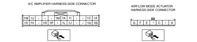
• Disconnect the airflow mode actuator connector.
• Connect battery positive voltage to airflow mode actuator terminal F (or terminal G) and ground to terminal G (or terminal F).
• Does the airflow mode actuator operate?
|
Yes
|
Connect the connector, then go to Step 3.
|
|
No
|
Go to the next step.
|
||
|
2
|
• Remove the airflow mode actuator.
• Operate the airflow mode main link manually.
• Does the airflow mode main link operate smoothly?
|
Yes
|
Replace the airflow mode actuator. (See AIRFLOW MODE ACTUATOR REMOVAL/INSTALLATION.)
|
|
No
|
Replace the airflow mode main link, airflow mode sub link, and the airflow mode crank.
|
||
|
3
|
• Disconnect the A/C amplifier connector (24-pin).
• Connect battery positive voltage to A/C amplifier connector (24-pin) terminal 1V (or terminal 1U) and ground to terminal 1U (or terminal 1V).
• Does the airflow mode actuator operate?
|
Yes
|
Inspect the connection at the A/C amplifier connector (24-pin). (See A/C AMPLIFIER INSPECTION [FULL-AUTO AIR CONDITIONER].)
|
|
No
|
Repair the wiring harness.
|
||
|
|
|||