|
1
|
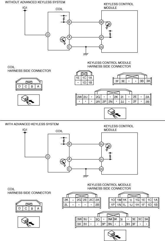
INSPECT COIL POWER SUPPLY SYSTEM
• Disconnect the coil connector.
• Turn the ignition switch to the ON position.
• Measure the voltage at coil connector terminal D.
-
― Is the voltage 8 V or more?
|
Yes
|
Go to the next step.
|
|
No
|
Repair the wiring harness.
|
|
2
|
INSPECT WIRING HARNESS BETWEEN COIL AND GROUND
• Turn the ignition switch to the LOCK position.
• Inspect the wiring harness between coil connector terminal C and ground for the following:
-
― Short to power supply
― Open circuit
• Is the wiring harness normal?
|
Yes
|
Go to the next step.
|
|
No
|
Repair the wiring harness.
|
|
3
|
INSPECT COIL INPUT SIGNAL CIRCUIT
• Connect the coil connector.
• Turn the ignition switch to the ON position.
• Measure the voltage at coil connector terminal B.
-
― Is the voltage 8 V or more?
|
Yes
|
Go to Step 7.
|
|
No
|
Go to the next step.
|
|
4
|
INSPECT COIL INPUT SIGNAL CIRCUIT
• Turn the ignition switch to the LOCK position.
• Disconnect the keyless unit connector.
• Turn the ignition switch to the ON position.
• Measure the voltage at keyless unit connector terminal 3E (without advanced keyless system)/3U (with advanced keyless system).
-
― Is the voltage 8 V or more?
|
Yes
|
Replace the keyless unit and perform procedures for when replacing the keyless unit only.
|
|
No
|
Go to the next step.
|
|
5
|
INSPECT COMMUNICATION CIRCUIT (INPUT) FOR CONTINUITY
• Turn the ignition switch to the LOCK position.
• Is there continuity between coil connector terminal B and keyless unit connector terminal 3E (without advanced keyless system)/3U (with advanced keyless system)?
|
Yes
|
Go to the next step.
|
|
No
|
Repair the wiring harness.
|
|
6
|
INSPECT COIL INPUT SIGNAL CIRCUIT
• Measure the resistance between coil connector terminal B and ground.
-
― Is the resistance 10 kilohms or more?
|
Yes
|
Replace the coil.
|
|
No
|
Repair the wiring harness.
|
|
7
|
INSPECT COIL OUTPUT SIGNAL CIRCUIT
• Connect the coil connector and the keyless unit connector.
• Turn the ignition switch to the ON position.
• Measure the voltage at coil connector terminal A.
-
― Is the voltage 8 V or more? (without advanced keyless system)
― Is the voltage 5 V or more? (with advanced keyless system)
|
Yes
|
Replace the coil.
|
|
No
|
Go to the next step.
|
|
8
|
INSPECT COIL OUTPUT SIGNAL CIRCUIT
• Turn the ignition switch to the LOCK position.
• Disconnect the coil connector.
• Turn the ignition switch to the ON position.
• Measure the voltage at coil connector terminal A.
-
― Is the voltage 8 V or more? (without advanced keyless system)
― Is the voltage 5 V or more? (with advanced keyless system)
|
Yes
|
Replace the coil.
|
|
No
|
Go to the next step.
|
|
9
|
INSPECT COMMUNICATION CIRCUIT (OUTPUT) FOR CONTINUITY
• Turn the ignition switch to the LOCK position.
• Disconnect the keyless unit connector.
• Is there continuity between coil connector terminal A and keyless unit connector terminal 3F (without advanced keyless system)/3V (with advanced keyless system)?
|
Yes
|
Go to the next step.
|
|
No
|
Repair the wiring harness.
|
|
10
|
INSPECT COIL OUTPUT SIGNAL CIRCUIT
• Measure the resistance between keyless unit connector terminal 3F (without advanced keyless system)/3V (with advanced keyless system) and ground.
-
― Is the resistance 10 kilohms or more?
|
Yes
|
Replace the keyless unit and perform procedures for when replacing the keyless unit only.
|
|
No
|
Repair the wiring harness.
|