CAN SYSTEM DESCRIPTION
id094000101000
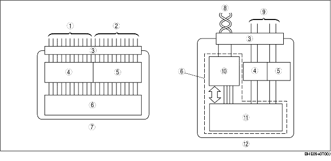
Mechanism of CAN System-Related Module
• A CAN system-related module is composed of an electrical circuit, CPU, and input/output interface.
• The size of the module has been reduced due to the elimination of the bulky, superfluous, input/output interface in the conventional type of electrical module.
• The CPU (multiplex block) controls all signals exchanged on the CAN harness.
• Communication with non-multiplex parts is carried out by conventional input/output interface.
• The functions of each component are shown below.
|
Component
|
Function
|
|
Electrical circuit
|
Supplies power to CPU and vicinity, and to input/output interface.
|
|
CPU
|
Computation processing block
|
Control function has been expanded, and when transmission is necessary, transmitted data is stored in a multiplex block. If a multiplex block receives a request to read stored data, transmitted data is read from the multiplex block.
|
|
Multiplex block
|
Transmits data received from bus line to computation processing block. In addition, sends transmitted data stored from computation processing block to bus line.
|
|
Input/Output interface
|
Electrically converts information signals from switches to, be input to CPU, and signals output from CPU for operating actuator or indicator lights.
|
|
1
|
Input signal
|
|
2
|
Output signal
|
|
3
|
Connector
|
|
4
|
Input interface
|
|
5
|
Output interface
|
|
6
|
CPU
|
|
7
|
Conventional module
|
|
8
|
Can harness (twisted pair)
|
|
9
|
Conventional wiring harness
|
|
10
|
Maltiplex block
|
|
11
|
Computation processing block
|
|
12
|
Can system-related module
|
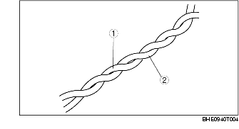
Twisted Pair
• The multichannel use two spirally twisted wires called a twisted pair, and each wire, CAN_L and CAN_H, has its own special function.
• Both bus lines are opposite phase voltage. This allows for minimal noise being emitted and makes if difficult for noise interference to be received.
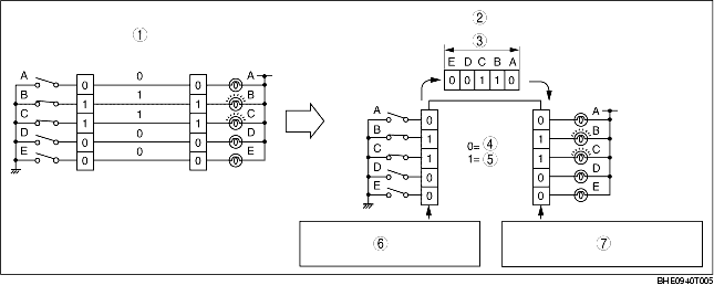
Time Division Multiplex
• For information exchange between electrical modules in a conventional system, a wire connection was necessary for each information signal. However, by sending the different signal at varying times over one channel, it is possible to send a large amount of information via a small harness.
• In the conventional, non-multiplex system, in order to control the illumination of the five bulbs, one switch and one channel was necessary for each bulb. For bulbs B and C to illuminate, switches B and C must be ON and electricity must flow through the channel. With the time multiplex system, this can be done through one channel. The channel is comprised of five data signal transmitters which transmit either a "0" or "1" signal to indicate whether a bulb turns ON or OFF. For example, to illuminate bulbs B and C, transmitters B and C transmit a "1" and transmitters A, D, and E transmit a "0". When the receiver receives these signal, bulbs B and C illuminate.
|
1
|
Non-multiplex system
|
|
2
|
Time division multiplex system
|
|
3
|
Data
|
|
4
|
OFF
|
|
5
|
ON
|
|
6
|
Each signal is transmitted one by one through the channel as it is received.
|
|
7
|
Each signal is output one by one as it is received from the channel.
|
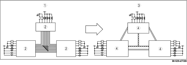
Vehicle CAN System
• By rearranging the multiple signal, common information between the CAN system-related modules is transmitted and received through the multichannel.
• The signal transmitted by one CAN system-related module is sent through the multichannel to all the CAN system-related modules, but only the concerned module(s) receives the signal and performs the appropriate operation (ex. light illumination, fan operation).
|
1
|
Conventional system
|
|
2
|
Electrical module
|
|
3
|
CAN system
|
|
4
|
CAN system-related module
|
CAN Signal-Chart
OUT: Output (sends signal)
IN: Input (receives signal)
|
Signal
|
Multiplex module
|
|
PCM
|
EPS control module
|
Keyless unit
|
TCM (AT)
|
DSC HU/CM
|
Steering angle sensor
|
Instrument cluster
|
|
Immobilizer-related information
|
OUT
|
-
|
IN
|
-
|
-
|
-
|
-
|
|
IN
|
-
|
OUT
|
-
|
-
|
-
|
-
|
|
Engine speed
|
OUT
|
IN
|
IN
|
IN
|
IN
|
-
|
IN
|
|
Vehicle speed
|
OUT
|
IN
|
-
|
-
|
-
|
-
|
IN
|
|
IN
|
-
|
-
|
OUT
|
-
|
-
|
-
|
|
Throttle valve opening angle
|
OUT
|
-
|
-
|
IN
|
IN
|
-
|
-
|
|
Engine coolant temperature
|
OUT
|
-
|
-
|
IN
|
-
|
-
|
IN
|
|
Engine torque
|
OUT
|
-
|
-
|
IN
|
IN
|
-
|
IN
|
|
Torque reduction disabled
|
OUT
|
-
|
-
|
IN
|
IN
|
-
|
-
|
|
Travelled distance
|
OUT
|
-
|
-
|
-
|
-
|
-
|
IN
|
|
-
|
-
|
-
|
-
|
OUT
|
-
|
IN
|
|
Fuel injection amount
|
OUT
|
-
|
-
|
-
|
-
|
-
|
IN
|
|
Engine oil pressure
|
OUT
|
-
|
-
|
-
|
-
|
-
|
IN
|
|
Engine oil level
|
OUT
|
-
|
-
|
-
|
-
|
-
|
IN
|
|
Engine coolant level
|
OUT
|
-
|
-
|
-
|
-
|
-
|
IN
|
|
Fuel pump status
|
OUT
|
-
|
-
|
-
|
-
|
-
|
IN
|
|
MIL on request
|
OUT
|
-
|
-
|
-
|
-
|
-
|
IN
|
|
IN
|
-
|
-
|
OUT
|
-
|
-
|
-
|
|
Generator warning light on request
|
OUT
|
-
|
-
|
-
|
-
|
-
|
IN
|
|
Transmission/axle specifications
|
OUT
|
-
|
-
|
-
|
IN
|
-
|
-
|
|
Tire size
|
OUT
|
-
|
-
|
-
|
IN
|
-
|
-
|
|
Cruise control main indicator light on request
|
OUT
|
-
|
-
|
IN
|
-
|
-
|
IN
|
|
Cruise control indicator light on request
|
OUT
|
-
|
-
|
IN
|
-
|
-
|
IN
|
|
Downshift request
|
OUT
|
-
|
-
|
IN
|
-
|
-
|
-
|
|
EPS warning light on request
|
-
|
OUT
|
-
|
-
|
-
|
-
|
IN
|
|
Idle speed increase request
|
IN
|
OUT
|
-
|
OUT
|
-
|
-
|
-
|
|
Ignition switch off time
|
IN
|
-
|
OUT
|
-
|
-
|
-
|
-
|
|
Target torque
|
IN
|
-
|
-
|
OUT
|
-
|
-
|
-
|
|
Torque upper limit
|
IN
|
-
|
-
|
OUT
|
-
|
-
|
-
|
|
Turbine shaft speed
|
IN
|
-
|
-
|
OUT
|
-
|
-
|
-
|
|
Target gear position/selector lever position
|
IN
|
-
|
-
|
OUT
|
IN
|
-
|
IN
|
|
Gear ratio
|
IN
|
-
|
-
|
OUT
|
-
|
-
|
-
|
|
Brake system status (EBD/ABS/DSC)
|
IN
|
IN
|
-
|
IN
|
OUT
|
-
|
IN
|
|
Torque reduction request
|
IN
|
-
|
-
|
OUT
|
OUT
|
-
|
-
|
|
Wheel speed (LF, RF, LR, RR)
|
IN
|
-
|
-
|
-
|
OUT
|
-
|
-
|
|
Wheel speed status (LF, RF, LR, RR)
|
IN
|
-
|
-
|
-
|
OUT
|
-
|
-
|
|
Steering angle
|
-
|
-
|
-
|
-
|
IN
|
OUT
|
-
|
|
Steering angle sensor status (sensor malfunction, circuit malfunction)
|
-
|
-
|
-
|
-
|
IN
|
OUT
|
-
|
|
Fuel tank level
|
IN
|
-
|
-
|
-
|
-
|
-
|
OUT
|
|
Parking brake position
|
-
|
-
|
-
|
-
|
IN
|
-
|
OUT
|
|
AT warning light on request
|
-
|
-
|
-
|
OUT
|
-
|
-
|
IN
|
On-Board Diagnostic Function
• The on-board diagnostic function is incorporated into the PCM, TCM, DSC HU/CM, keyless unit, EPS control module and instrument cluster. This function can narrow down CAN system malfunction locations.
• The on-board diagnostic function consists of the following functions.
-
– Failure detection function, which detects DTCs malfunctions in CAN system-related parts.
-
– Memory function, which stores detected.
-
– Self-malfunction diagnostic function, which indicates system malfunctions using DTCs and warning lights.
-
– PID/DATA monitoring function, which verifies the input/output condition of specific input/output signals being read out.
• Using the WDS or equivalent, DTCs can be read out and deleted, and the PID/DATA monitoring function can be activated.
• The CAN system has a fail-safe function. When a malfunction occurs in CAN system, the transmission module sends a warning signal and the receiving module illuminates the warning light.
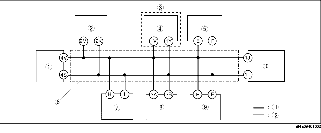
Block diagram
|
1
|
PCM
|
|
2
|
EPS control module
|
|
3
|
AT
|
|
4
|
TCM
|
|
5
|
Steering angle sensor
|
|
6
|
Twisted pair
|
|
7
|
DSC HU/CM
|
|
8
|
Keyless unit
|
|
9
|
DLC-2
|
|
10
|
Instrument cluster
|
|
11
|
CAN_H
|
|
12
|
CAN_L
|
Failure detection function
-
• The failure detection function in each CAN system-related module detects malfunctions in input/output signals.
-
• This function outputs the DTC for the detected malfunction to the DLC-2, and also sends the detected result to the memory function and fail-safe function.
Fail-safe function
-
• When the failure detection function determines that there is a malfunction, the fail-safe function illuminates a warning light to inform the driver of the malfunction.
|
Module
|
Fail-safe function
|
|
PCM
|
• MIL illuminated
|
|
EPS control module
|
• EPS warning light illuminated
|
|
Keyless unit
|
-
|
|
TCM
|
• AT warning light illuminated
|
|
DSC HU/CM
|
• ABS suspended
• TCS suspended
• DSC suspended
• ABS warning light illuminated
• DSC indicator light illuminated
• DSC OFF light illuminated
|
|
Steering angle sensor
|
• Send malfunction data to DSC HU/CM
|
|
Instrument cluster
|
• Speedometer, tachometer, water temperature gauge, oil pressure gauge: 0 displayed
|
Memory function
-
• The memory function stores the DTC for the malfunction of input/output signals for related parts, as determined by the failure detection function.
Self-malfunction diagnostic function
-
• The self-malfunction diagnostic function determines that there is a malfunction, and outputs a signal, as a DTC, to the DLC-2. The DTC can be read out using the WDS or equivalent.
DTC table
|
DTC
|
Malfunction location
|
DTC output module
|
|
U0073
|
CAN system communication error
|
• PCM
• TCM
• EPS control module
• Keyless unit
|
|
U0100
|
Communication error to PCM
|
TCM
|
|
U0101
|
Communication error to TCM
|
PCM
|
|
U0121
|
Communication error to DSC HU/CM
|
PCM
|
|
U0155
|
Communication error to instrument cluster
|
|
U2510
|
Communication error to PCM
|
Keyless unit
|
|
U1147
|
|
U1900
|
CAN system communication error
|
• DSC HU/CM
• EPS control module
• Steering angle sensor
• Keyless unit
• Instrument cluster
|
|
U2516
|
CAN system wiring harness open or short circuit
|
• DSC HU/CM
• Steering angle sensor
• Instrument cluster
|
PID/DATA monitoring function
-
• The PID/DATA monitoring function is used to freely select and read out, in real time, the monitored items for the input/output signals of the instrument cluster.
-
• The WDS or equivalent is used to read out the PID/DATA monitor information.
|
PID name (definition)
|
Condition
|
Specification
|
PID monitor module
|
Terminal
|
|
ABS_MSG
(Missing message from the DSC HU/CM)
|
Present
|
Circuit in the DSC HU/CM is normal
|
Instrument cluster
|
• DSC HU/CM: H, I
• Instrument cluster: 1J, 1L
|
|
Not Present
|
Circuit in the DSC HU/CM is disable
|
|
TCM_MSG
(Missing message from the TCM)
|
Present
|
Circuit in the TCM is normal
|
• TCM: 1V, 1Y
• Instrument cluster: 1J, 1L
|
|
Not Present
|
Circuit in the TCM is disable
|
|
EPS_MSG
(Missing message from the EPS control module)
|
Present
|
Circuit in the EPS control module is normal
|
• EPS control module: 2K, 2M
• Instrument cluster: 1J, 1L
|
|
Not Present
|
Circuit in the EPS control module is disable
|
|
PCM_MSG
(Missing message from the PCM)
|
Present
|
Circuit in the PCM is normal
|
• PCM: 4S, 4V
• Instrument cluster: 1J, 1L
|
|
Not Present
|
Circuit in the PCM is disable
|
Narrowing down malfunction locations
-
• The on-board diagnostic function, by verifying the detected DTC and PID/DATA monitor information from each module, can narrow down a CAN system malfunction location. Refer to the Self-malfunction diagnostic Function and PID/DATA monitoring function for detailed information regarding DTCs and the PID/DATA monitor. (See Self-malfunction diagnostic function.) (See PID/DATA monitoring function.)
Flowchart
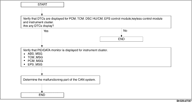
Example (PCM-related communication error)
-
Note
-
• This example is for MT with DSC.
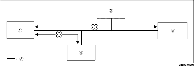
1. DTCs for the PCM, DSC HU/CM and instrument cluster can be verified using the WDS or equivalent.
|
Module
|
Displayed DTC
|
Probable malfunction location
|
|
PCM
|
U0073
|
PCM-related CAN system malfunction
|
|
U0121
|
Communication error between PCM and DSC HU/CM
|
|
U0155
|
Communication error between PCM and instrument cluster
|
|
DSC HU/CM
|
U1900, U2516
|
DSC HU/CM-related CAN system malfunction
|
|
Instrument cluster
|
U1900, U2516
|
Instrument cluster-related CAN system malfunction
|
|
1
|
PCM
|
|
2
|
DLC-2
|
|
3
|
Instrument cluster
|
|
4
|
DSC HU/CM
|
|
5
|
Twisted pair
|
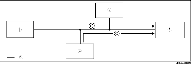
2. PID/DATA monitor information for the instrument cluster can be verified using the WDS or equivalent.
|
Module
|
PID name (definition)
|
Condition
|
Probable malfunction point
|
|
Instrument cluster
|
PCM_MSG
(Missing message from the PCM)
|
Not Present
|
Communication error between instrument cluster and PCM
|
|
ABS_MSG
(Missing message from the DSC HU/CM)
|
Present
|
Normal communication between instrument cluster and DSC HU/CM
|
|
1
|
PCM
|
|
2
|
DLC-2
|
|
3
|
Instrument cluster
|
|
4
|
DSC HU/CM
|
|
5
|
Twisted pair
|
3. If there is a communication error between the instrument cluster and PCM, even if the communication between the DSC HU/CM and the instrument cluster is normal, it is probable that there is a malfunction in the PCM or PCM-related wiring harnesses.