CYLINDER BLOCK ASSEMBLY(I)


BME011010300507

Note
• The internal parts of the cylinder block will not be available for the "TRIBUTE (L.H.D.) Face-lifted model"
(Refer to TRIBUTE Workshop Manual for identifying Face-lifted model.)

1. Assemble in the order indicated in the table.

.

1
Upper cylinder block
2
Upper main bearing, thrust bearing
3
Crankshaft
4
Lower main bearing, thrust bearing
5
Lower cylinder block
6
Piston
7
Connecting rod
8
Piston pin
9
Snap ring
10
Piston ring
11
Piston, connecting rod
12
Connecting rod bearing
13
Connecting rod cap

Lower Cylinder Block Assembly Note

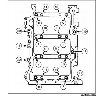
1. Apply a continuous bead of silicone sealant to the upper cylinder block as indicated in the figure.

Caution
• Because bolts 1-16 are pliant bolts, they cannot be reused. Replace bolts 1-8 with new bolts and use bolts 9-16 installed during inspection when assembling the lower cylinder block.

2. Install the lower cylinder block bolts in the order indicated in the figure.

Tightening torque
3.0-5.0 N·m {30-51 kgf·cm, 27-44 in·lbf}

Hole No.

Bolt

Description

18, 19, 20, 21, 22

M8×1.25×79.3
bolt
1, 2, 3, 4, 17

M8×1.25×95.3
bolt
13, 14, 15, 16

M10×1.5×106
bolt
5, 6, 7, 8

M6×1.0×19.5/
M8×1.25×95.3
stud
9, 10, 11, 12

M10×1.5×105.5/
M8×1.25×95.1
stud

3. Push crankshaft forward and then rearward to seat the crankshaft thrust washer.

4. Tighten the lower cylinder block bolts in the order indicated in the figure in four steps.

(1) Bolts 1-8: tighten to 22-28 N·m {2.2-2.9 kgf·m, 16-20 ft·lbf}.
(2) Bolts 9-16: tighten to 37-43 N·m {3.7-4.4 kgf·m, 27-31 ft·lbf}.
(3) Bolts 1-16: tighten 85°-95°.
(4) Bolts 17-22: tighten to 20-30 N·m {2.1-3.0 kgf·m, 15-22 ft·lbf}.
(5) Verify that the crankshaft rotates freely.

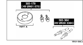
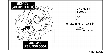
5. Assemble rear oil seal with part A of the SST [303-178 (49 UN01 070)] and the SST [303-384 (49 UN30 3384)].

(1) Install the studs of the SST [303-384 (49 UN30 3384)] as indicated in the figure.

(2) Apply clean engine oil to the oil seal.
(3) Push the oil seal slightly in by hand.
(4) Install part A of the SST [303-178 (49 UN01 070)] and compress the oil seal with the nuts of the SST [303-384 (49 UN30 3384)].

Piston Pin Assembly Note

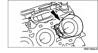
1. Assemble the piston pin so that connecting rod's projection for discrimination faces opposite side of the arrow mark on the piston (rear side of the engine).

2. Apply clean engine oil to the piston pin.

3. Install the piston pin until the pin contacts the clip.

• If the pin cannot be installed easily, heat the piston.

Piston Ring Assembly Note

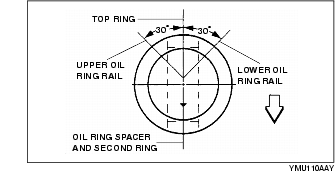
1. Install the two oil control ring segments and spacer.

2. Verify that the second ring is installed with scraper face side downward.

3. Install the top ring.

Piston, Connecting Rod Assembly Note

1. Position the end gap of each ring as indicated in the figure.

2. Insert the piston and connecting rod into the cylinder with the arrow mark to front of the engine.

Connecting Rod Cap Assembly Note

Caution
• Because the connecting rod bolts are pliant bolts, they cannot be reused. Use the bolts installed during inspection when assembling the connecting rod cap.
Note
• When assembling the connecting rods and connecting rod caps, it is imperative that bearing slots and tangs be located on the same side of the connecting rods.

1. Install the connecting rod bolts to the connecting rod cap by tapping the bolt with a plastic hammer.

2. Tighten the connecting rod bolts in three steps.

(1) Tighten to 20-25 N·m {2.0-2.6 kgf·m, 15-18 ft·lbf}.
(2) Tighten to 40-45 N·m {4.0-4.6 kgf·m, 29-33 ft·lbf}.
(3) Tighten 90°-120°.