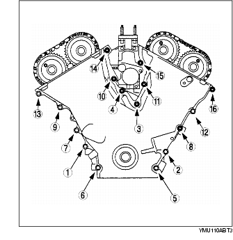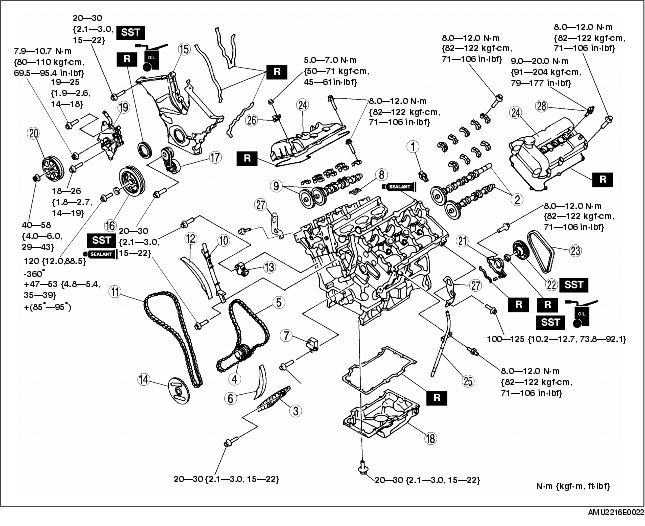
1. Assemble in the order indicated in the table.
.
|
1
|
Rocker arm (LH)
|
|
2
|
Camshaft (LH)
|
|
3
|
Chain guide (LH)
|
|
4
|
Crankshaft timing sprocket
|
|
5
|
Timing chain (LH)
|
|
6
|
Tensioner arm (LH)
|
|
7
|
Chain tensioner (LH)
|
|
8
|
Rocker arm (RH)
|
|
9
|
Camshaft (RH)
|
|
10
|
Chain guide (RH)
|
|
11
|
Timing chain (RH)
|
|
12
|
Tensioner arm (RH)
|
|
13
|
Chain tensioner (RH)
|
|
14
|
CKP sensor pulse wheel
|
|
15
|
Engine front cover
|
|
16
|
Crankshaft pulley
|
|
17
|
Auto tensioner
|
|
18
|
Oil pan
(See Oil Pan Assembly Note)
|
|
19
|
P/S oil pump
|
|
20
|
P/S oil pump pulley
|
|
21
|
Camshaft oil seal housing
|
|
22
|
Water pump drive pulley
|
|
23
|
Water pump drive belt
|
|
24
|
Cylinder head cover
|
|
25
|
Oil level gauge, pipe
|
|
26
|
Condenser
|
|
27
|
Engine hanger
|
|
28
|
Spark plug
|
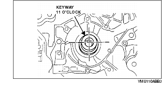
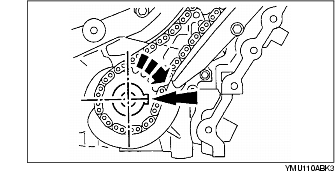
1. Turn the crankshaft clockwise to position the crankshaft keyway in the 11 o'clock position.
2. Install the camshafts (LH).
3. Hand tighten the camshaft (LH) caps in their original positions.
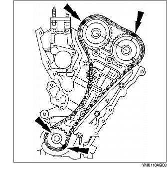
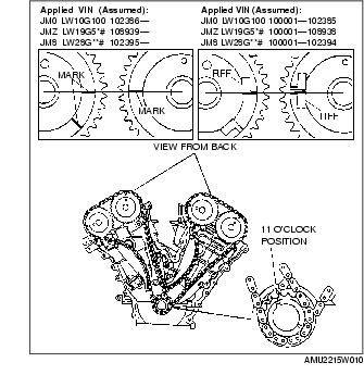
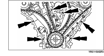
1. Install the timing chain (LH) by aligning the colored links on the timing chain (LH) with the marks on the timing sprockets.

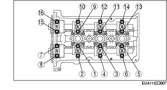
2. Align the camshaft end play using the camshaft bearing thrust caps 1L and 5L, and tighten the other bearing caps.
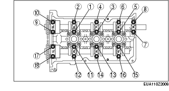
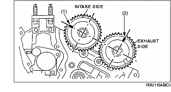
3. Tighten the bearing caps in the order indicated in the figure in several passes.
Water pump drive pulley on intake camshaft side
Water pump drive pulley on exhaust camshaft side
1. Turn the crankshaft clockwise to position the crankshaft keyway in the 3 o'clock position.
2. Install the camshafts (RH).

3. Hand tighten the camshaft caps (RH) in their original positions.
1. Install the timing chain (RH) by aligning the colored links on the timing chain (RH) with the marks on the timing sprockets.

2. Align the camshaft end play using the camshaft bearing thrust caps 1R and 5R, and tighten the other bearing caps.
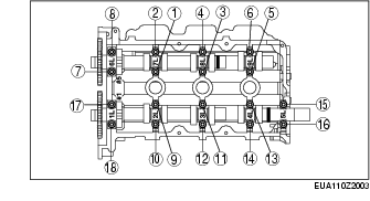
3. Tighten the bearing caps in the order indicated in the figure in several passes.
4. Install the chain tensioner and remove the retaining wire.
5. Turn the crankshaft clockwise 1 and 2/3 turns to position the crankshaft keyway in the 11 o'clock position.
6. Verify that marks on the camshaft sprockets are aligned.
1. Using the keyway marked 25/34Y (blue paint stripe), install the rotor with the indentation towards the front.
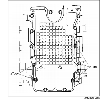
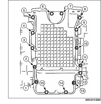
1. Apply a 6 mm {0.24 in} dot of silicon sealant as indicated in the figure (mating faces).
2. Tighten the bolts and studs in the order indicated in the figure.
|
Hole No.*2
|
Bolt
|
Description
|
|---|---|---|
|
2, 5, 6, 7, 9, 12, 13
|
|
M8×1.25×51.8
bolt
|
|
3, 4, 8, 10, 11, 14, 15, 16
|
|
M6×1.0×20/
M8×1.25×40
stud
|
|
1
|
|
M6×1.0×20/
M8×1.25×47.5
stud
|
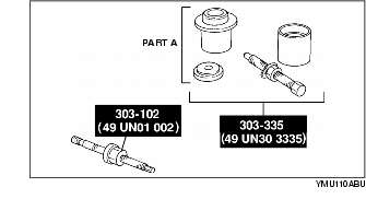
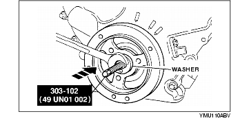
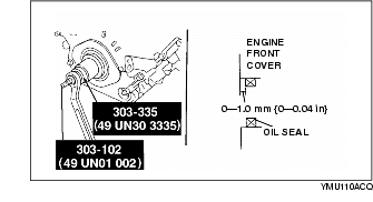
3. Assemble the front oil seal using part A of the SST [303-335 (49 UN30 3335)] and the SST [303-102 (49 UN01 002)] in the following order.
1. Using the silicone sealant, seal the keyway in the crankshaft pulley.
2. Install the crankshaft pulley using the SST and washer of crankshaft pulley lock bolt washer.
3. Hold the crankshaft using the SST.
4. Tighten the crankshaft pulley lock bolt in four steps.
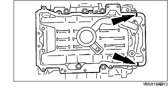
1. Apply silicone sealant to the mating faces as indicated in the figure.
Dot diameter
2. Install the oil pan with a new gasket.
3. Install the bolts and studs as indicated in the figure.
4. Align the cylinder block and the rear face of the oil pan using the straight edge.
5. Tighten the bolts and studs in the order indicated in the figure.
6. Measure the height between the cylinder block and the oil pan.
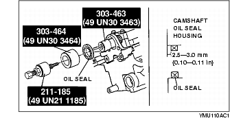
1. Apply clean engine oil to the oil seal.
2. Install the camshaft oil seal using the SSTs.
1. Install the water pump pulley using the SST.
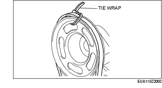
1. Secure the water pump drive pulley and the belt using a tie wrap.
2. Rotate the crankshaft verifying that the belt engages properly.
3. Verify that the belt is installed securely in the pulley groove.
4. Remove the tie wrap.
1. Apply silicone sealant to the mating faces as indicated in the figure.
2. Install the cylinder head cover with a new gasket.
3. Tighten the bolts in the order indicated in the figure.