CLUTCH COMPONENT DISASSEMBLY
BUE051719500A02
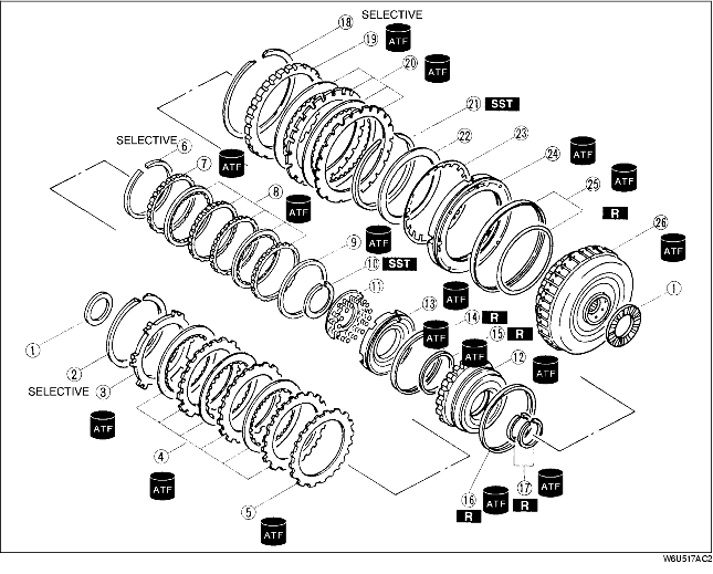
1. Disassemble in the order indicated in the table.
.
|
1
|
Thrust bearing
|
|
2
|
Snap ring
|
|
3
|
Retaining plate
|
|
4
|
Drive and driven plates
|
|
5
|
Dished plate
|
|
6
|
Snap ring
|
|
7
|
Retaining plate
|
|
8
|
Drive and driven plates
|
|
9
|
Dished plate
|
|
10
|
Snap ring (coasting clutch)
|
|
11
|
Spring and retainer
|
|
12
|
Coasting clutch drum
|
|
13
|
Coasting clutch piston
|
|
14
|
Outer seal
|
|
15
|
Inner seal
|
|
16
|
Outer seal
|
|
17
|
Seal rings
|
|
18
|
Snap ring
|
|
19
|
Retaining plate
|
|
20
|
Drive and driven plates
|
|
21
|
Snap ring (reverse clutch)
|
|
22
|
Return spring stopper
|
|
23
|
Piston return spring
|
|
24
|
Reverse piston
|
|
25
|
Seal rings
|
|
26
|
Reverse and forward drum
|
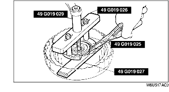
Snap Ring (Coasting Clutch) Disassembly Note
-
Caution
-
• Depress the spring retainer only enough to remove the snap ring. Overpressing will damage the retainer assembly edges.
1. Install the SSTs in the coasting clutch drum as shown.
2. Compress the spring and retainer.
3. Remove the snap ring.
4. Remove the SSTs, and remove the spring and retainer.
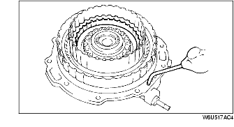
Coasting Clutch Drum Disassembly Note
1. Set the reverse and forward drum onto the oil pump.
-
Warning
-
• Using compressed air can cause dirt and other particles to fly out, causing injury to the eyes. Wear protective eye wear whenever using compressed air.
2. Remove the coasting clutch piston from the reverse and forward drum by applying compressed air through the fluid passage.
-
Air pressure
-
390 kPa {4.0 kgf/cm2, 57 psi} max.
Coasting Clutch Piston Disassembly Note
-
Warning
-
• Using compressed air can cause dirt and other particles to fly out, causing injury to the eyes. Wear protective eye wear whenever using compressed air.
1. Remove the coasting clutch piston from the coasting clutch drum by applying compressed air through the fluid passage.
-
Air pressure
-
390 kPa {4.0 kgf/cm2, 57 psi} max.
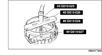
Snap Ring (Reverse Clutch) Disassembly Note
-
Caution
-
• Depress the spring retainer only enough to remove the snap ring. Overpressing will damage the retainer assembly edges.
1. Install the SSTs in the reverse and forward drum as shown.
2. Compress the piston return spring.
3. Remove one end of the snap ring from the grove using snap ring pliers.
4. Remove the SSTs from the reverse and forward drum.
5. Remove the snap ring.
Reverse Piston Disassembly Note
-
Warning
-
• Using compressed air can cause dirt and other particles to fly out, causing injury to the eyes. Wear protective eye wear whenever using compressed air.
1. Set the reverse and forward drum onto the oil pump.
2. Remove the reverse piston by applying compressed air through the fluid passage.
-
Air pressure
-
390 kPa {4.0 kgf/cm2, 57 psi} max.