 |
atraaw00000252
ENGINE REMOVAL[AJ (3.0L Duratec)]
id0110a3802200
1. Remove the plug hole plate.
2. Remove the battery tray. (See BATTERY REMOVAL/INSTALLATION[AJ (3.0L Duratec)].)
3. Remove the air cleaner outlet tube and air cleaner. (See AIR CLEANER REMOVAL/INSTALLATION[AJ (3.0L Duratec)].)
4. Lift up the vehicle.
5. Remove the lower splash shield.
6. Drain the engine coolant. (See ENGINE COOLANT REPLACEMENT[AJ (3.0L Duratec)].)
7. Drain the engine oil. (See ENGINE OIL REPLACEMENT[AJ (3.0L Duratec)].)
8. Lower the vehicle.
9. Disconnect the fuel line. (See BEFORE SERVICE PRECAUTION[AJ (3.0L Duratec)].)
10. Remove the water pump drive belt. (See DRIVE BELT REMOVAL/INSTALLATION[AJ (3.0L Duratec)].)
11. Disconnect the accelerator cable.
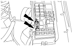
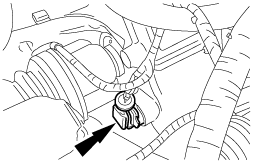
12. Disconnect purge solenoid valve outlet tube.
atraaw00000252
|
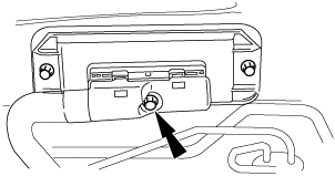
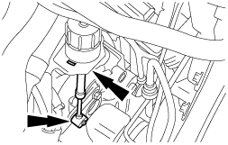
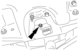
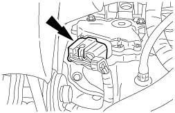
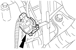
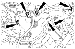
13. Disconnect the PCM connector.
atraaw00000378
|
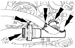
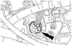
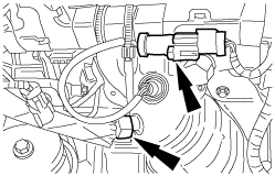
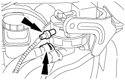
14. Disconnect the hoses and position the thermostat housing and hose assembly out of the way.
atraaw00000912
|
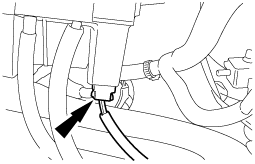
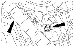
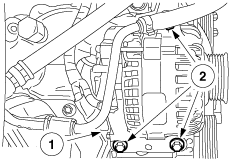
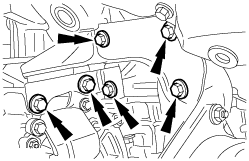
15. Disconnect the connector from BJB.
atraaw00000256
|
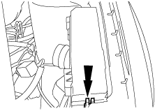
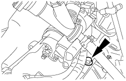
16. Remove the BJB cover.
atraaw00000257
|
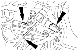
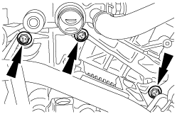
17. Remove the nuts and the cables.
atraaw00002973
|
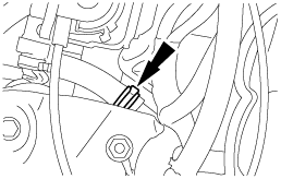
18. Disconnect the selector cable.
atraaw00000333
|
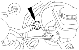
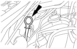
19. Disconnect the brake vacuum hose.
atraaw00000260
|
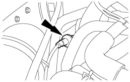
20. Disconnect the vacuum line.
atraaw00000261
|
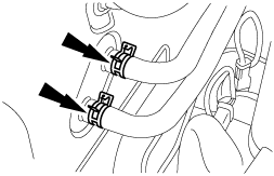
21. Disconnect the heater hoses.
atraaw00000262
|
22. Disconnect the power steering return line.
atraaw00000263
|
23. Disconnect the power steering pressure line.
atraaw00000264
|
24. Remove the dipstick.
atraaw00000265
|
25. Remove the front pipe. (See FRONT PIPE REMOVAL/INSTALLATION[AJ (3.0L Duratec)].)
26. Remove the catalytic converter. (See CATALYTIC CONVERTER REMOVAL/INSTALLATION[AJ (3.0L Duratec)].)
27. Remove the A/C compressor. Do not disconnect the A/C compressor pipe while positioning it out of the way.
28. Remove both the front wheels and tires. (See WHEEL AND TIRE REMOVAL/INSTALLATION.)
29. Remove the propeller shaft. (See PROPELLER SHAFT REMOVAL/INSTALLATION.)
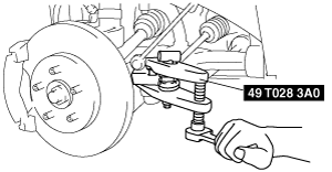
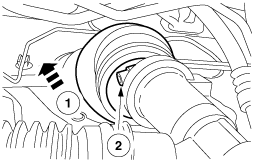
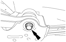
30. Separate the LH and RH ball joints.
atraaw00000266
|
31. Separate the LH and RH tie-rod ends from the steering knuckle using the SST.
atraaw00000267
|
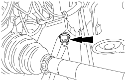
32. Separate the LH and RH stabilizer control link from the shock absorber.
atraaw00000268
|
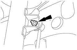
33. Remove the bolt and position the LH and RH ABS sensors out of the way.
atraaw00000269
|
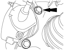
34. Remove the LH and RH brake calipers from the steering knuckles and support the struts.
atraaw00000270
|
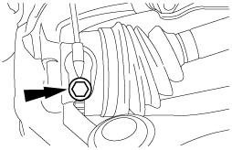
35. Remove the boot mounting nut.
36. Separate the bolt between the steering shaft and steering gear.
atraaw00000271
|
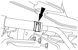
37. Remove the transaxle line bracket bolt.
atraaw00000272
|
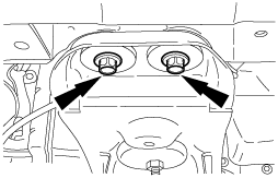
38. Disconnect the two transaxle cooler lines.
atraaw00000273
|
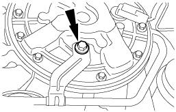
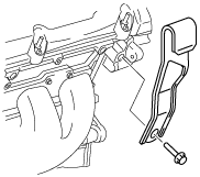
39. Remove the torque converter inspection cover.
atraaw00000274
|
40. Remove the torque converter nuts.
atraaw00000275
|
41. Remove the four bolts.
atraaw00000276
|
42. Determine the appropriate lift position.
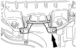
43. Remove the bolts and nuts, and then remove the No.3 engine mount bracket.
atraaw00000822
|
44. Remove the bolts and No.4 engine mount rubber.
atraaw00000278
|
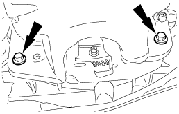
45. Remove two front cross member bolts.
atraaw00000279
|
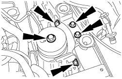
46. Remove two front cross member nuts.
atraaw00000280
|
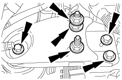
47. Remove the four bolts from the engine mount member.
atraaw00000281
|
48. Remove the transaxle from the vehicle.
49. Remove the power steering pressure hose bracket.
atraaw00003213
|
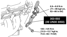
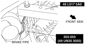
50. Assemble two SSTs using the bolt (M6) and nut, then install them in the position shown in the figure for the cylinder head (RH).
atraaw00003214
|
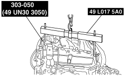
atraaw00000062
|
51. Using the SST, remove the transaxle from the lift and set it down on the floor or a suitable table.
atraaw00000283
|
52. Disconnect the HO2S.
atraaw00000284
|
53. Disconnect the TR switch.
atraaw00000285
|
54. Disconnect the transaxle connector.
atraaw00000286
|
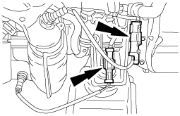
55. Remove the bolt and separate the transaxle control harness from the bracket.
atraaw00000287
|
56. Remove the two bolts, the starter and wiring harness.
atraaw00000288
|
57. Disconnect the KS jumper electrical connector.
atraaw00000289
|
58. Disconnect the OSS sensor electrical connector.
atraaw00000290
|
59. Disconnect the HO2S and the EGR tube from the exhaust manifold.
atraaw00000291
|
60. Remove the generator.
atraaw00000292
|
61. Remove the six RH exhaust manifold nuts and gasket.
atraaw00000293
|
62. Remove the bolts and position the joint bracket out of the way.
atraaw00000294
|
63. Remove the five transaxle bolts.
atraaw00000295
|
64. Remove the engine from the transaxle.