VALVE CLEARANCE INSPECTION[L3]


id0110a4803400

1.  Disconnect the negative battery cable.

2.  Remove the splash shield (RH).

3.  Remove the ignition coils. (See IGNITION COIL REMOVAL/INSTALLATION[L3])

4.  Disconnect the oil control valve (OCV) connector.

5.  Remove the ventilation hose.

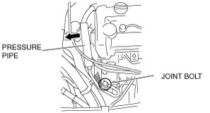
6.  Remove the pressure pipe bracket of the P/S oil pump.

7.  Loosen the pressure pipe joint bolt of the P/S oil pump, move the pressure pipe to the right side of the vehicle, position the cylinder head cover out of the way, and then temporarily tighten the bolt.

atraaw00002355

8.  Remove the cylinder head cover.

9.  Verify that the engine is in cold condition.

10.  Measure the valve clearance.

(1)  Turn the crankshaft clockwise so that the No.1 piston is at TDC of the compression stroke.
(2)  Measure the valve clearance at A in the figure.
•  If the valve clearance is out of the standard value, adjust it. (See VALVE CLEARANCE ADJUSTMENT[L3].)
Note
•  Make sure to note down the measured values for choosing the suitable replacement tappets.
Valve clearance [Engine cold]
IN: 0.22—0.28 mm {0.0087—0.0110 in}
EX: 0.27—0.33 mm {0.0106—0.0130 in}
atraaw00002265
(3)  Turn the crankshaft 360° clockwise so that the No.4 piston is at TDC of the compression stroke.
(4)  Measure the valve clearance at B in the figure.
•  If the valve clearance is out of the standard value, adjust it. (See VALVE CLEARANCE ADJUSTMENT[L3].)
Note
•  Make sure to note down the measured values for choosing the suitable replacement tappets.
Valve clearance [Engine cold]
IN: 0.22—0.28 mm {0.0087—0.0110 in}
EX: 0.27—0.33 mm {0.0106—0.0130 in}

11.  Install the cylinder head cover.

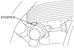
12.  Loosen the pressure pipe joint bolt, move the pressure pipe joint until it contacts the stopper to return the pipe to its original position and then tighten the bolt.

atraaw00002357

Caution
•  It is not necessary to replace the pressure hose joint seal and washer if only performing this procedure. A small amount of P/S fluid will leak from the joint. However, it is not necessary to perform the normal air bleeding procedure since air bleeding will occur when running the engine.
Tightening torque:
29.4—44.1 N·m {3.00—4.49 kgf·m, 21.7—32.5 ft·lbf}

13.  Install the pressure pipe bracket of the P/S oil pump.

14.  Install the ventilation hose.

15.  Connect the oil control valve connector.

16.  Install the ignition coils. (See IGNITION COIL REMOVAL/INSTALLATION[L3])

17.  Install the splash shield (RH).