|
atraaw00002437
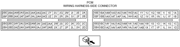
PCM INSPECTION [L3]
id0140a7802500
Using SST (M-MDS)
1. Connect the SST (M-MDS) to the DLC-2.
atraaw00002437
|
2. Turn the ignition switch to ON position.
3. Measure the PID value.
PID/DATA monitor table (reference)
|
Monitor item (Definition) |
Unit/Condition |
Condition/Specification (Reference) |
Action |
PCM terminal |
|
|---|---|---|---|---|---|
|
AC_REQ
(A/C request signal)
|
ON/OFF
|
A/C switch and fan switch ON at ignition switch ON: On
A/C switch OFF at ignition switch ON: Off
|
Inspect A/C switch.
|
1AP
|
|
|
ACCS
(A/C relay)
|
ON/OFF
|
Ignition switch ON: OFF
A/C switch ON and fan switch ON at idle: ON
|
Inspect following PIDs: RPM, ECT, TR.
Inspect A/C relay.
|
1AN
|
|
|
AFR (Air/fuel ratio)
|
—
|
Target air-oil ratio is displayed
|
• A/F sensor
|
2Z
2AC
2AD
|
|
|
AFR_ACT
(Actual air/fuel ratio)
|
—
|
Actual air-oil ratio is displayed
|
• A/F sensor
|
2Z
2AC
2AD
|
|
|
ALTF
(Generator field coil control duty value)
|
%
|
Ignition switch ON: 0%
Idle: 0—100%
Just after A/C switch ON and fan switch ON at idle: Duty value rises
|
Inspect following PIDs: IAT, ECT, RPM, VPWR, ALTT V.
Inspect generator.
|
2AQ
|
|
|
ALTT V
(Generator output voltage)
|
V
|
Ignition switch ON: 0 V
Idle: Approx. 14.9 V*1 (E/L not operating)
|
Inspect generator.
|
2AM
|
|
|
APP
(Accelerator pedal position)
|
%
|
APP released: 0%
APP open: 100%
|
Inspect following PIDs: APP1, APP2.
Inspect accelerator pedal position sensor.
|
1Y
1AG
|
|
|
APP1
(Accelerator pedal position sensor 1)
|
%
|
APP released: 31.0—32.4%
APP open: 69.8—81.8%
|
Inspect accelerator pedal position sensor.
|
1Y
|
|
|
V
|
APP released: Approx. 1.58 V
APP depressed: Approx. 3.90 V
|
||||
|
APP2
(Accelerator pedal position sensor 2)
|
%
|
APP released: 20.2—21.4%
APP depressed: 58.8—70.8%
|
Inspect accelerator pedal position sensor.
|
1AG
|
|
|
V
|
APP released: Approx. 1.03 V
APP depressed: Approx. 3.35 V
|
||||
|
ARPMDES
(Target engine speed)
|
RPM
|
No load: 650—750 rpm
E/L operating: 650—750 rpm
P/S operating: 650—750 rpm
A/C ON: 650—750 rpm
|
Inspect following PIDs: IAT, RPM, MAP, ECT, MAF, INGEAR, TR, PSP, ALTT V.
Inspect CKP sensor.
|
—
|
|
|
BOO
(Brake switch)
|
ON/OFF
|
Brake pedal depressed: ON
Brake pedal released: OFF
|
Inspect brake switch.
|
1AU
|
|
|
BPA
(Brake pressure applied switch)
|
ON/OFF
|
Brake pedal depressed: ON
Brake pedal released: OFF
|
Inspect brake switch.
|
—
|
|
|
CATT11_DSD
(Desired catalyst temperature bank one, sensor one)
|
°C
|
Indicate the estimated catalytic converter temperature
|
Perform applicable DTC troubleshooting.
(See DTC TABLE [L3].)
|
—
|
|
|
CHRGLP
(Generator warning light)
|
ON/OFF
|
Ignition switch ON: ON
Idle: OFF
|
Perform applicable DTC troubleshooting.
(See DTC TABLE [L3].)
|
—
|
|
|
COLP
(Refrigerant pressure switch (middle))
|
ON/OFF
|
Refrigerant pressure switch (middle) ON *2 at idle: ON
Refrigerant pressure switch (middle) OFF*3 at idle: OFF
|
Inspect refrigerant pressure switch.
|
1R
|
|
|
DTCCNT
(Number of DTC detected)
|
—
|
—
|
Perform applicable DTC troubleshooting.
(See DTC TABLE [L3].)
|
—
|
|
|
ECT
(Engine coolant temperature)
|
°C
|
°F
|
ECT 20 °C {68 °F}: 20 °C {68 °F}
ECT 60 °C {140 °F}: 60 °C {140 °F}
|
Inspect ECT sensor.
|
2AK
|
|
V
|
ECT 20 °C {68 °F}: 3.04—3.14 V
ECT 60 °C {140 °F}: 1.29—1.39 V
|
||||
|
EQ_RAT11
(Equivalence ratio (lambda))
|
—
|
Idling after warm-up: Approx. 1
|
Perform applicable DTC troubleshooting.
(See DTC TABLE [L3].)
|
2Z
2AC
2AD
|
|
|
EQ_RAT11_DSD
(Desired equivalence ratio (lambda))
|
—
|
Idling after warm-up: Approx. 1
|
Perform applicable DTC troubleshooting.
(See DTC TABLE [L3].)
|
—
|
|
|
ETC_ACT
(Electronic throttle control actual)
|
°
|
Indicate the desired TP by angle
|
Perform applicable DTC troubleshooting.
(See DTC TABLE [L3].)
|
2A
2B
|
|
|
ETC_DSD
(Electronic throttle control desired)
|
%
|
Indicate the desired TP by percent
|
Inspect following PIDs:APP1, APP2, ETC_ACT.
Inspect TP sensor.
|
—
|
|
|
°
|
Indicate the desired TP by angle
|
||||
|
EVAPCP
(Purge solenoid valve duty value)
|
%
|
Ignition switch ON: 0%
Idle: 0%
|
Inspect following PIDs: IAT, RPM, ECT, MAF, O2S11, INGEAR, TR, VPWR.
|
2AN
|
|
|
FAN1
(Cooling fan control)
|
ON/OFF
|
ECT below 100 °C {212 °F}: OFF
Others: ON
|
Inspect following PIDs: RPM, ECT, COLP, test.
Inspect cooling fan relay.
|
1D
|
|
|
FAN2
(Cooling fan control)
|
ON/OFF
|
ECT below 108 °C {226 °F}: OFF
A/C operating, refrigerant pressure switch (middle) is OFF, and ECT below 108 °C {226 °F}: OFF
Others: ON
|
Inspect following PIDs: RPM, ECT, COLP, test.
Inspect cooling fan relay.
|
1W
|
|
|
FP
(Fuel pump relay)
|
ON/OFF
|
Ignition switch ON: OFF
Idle: ON
Cranking: ON
|
Inspect following PIDs: RPM.
Inspect fuel pump relay.
|
1AR*4
1AQ*5
|
|
|
FUELPW
(Fuel injector duration)
|
ms
|
Ignition switch ON: 0 ms
Idle (after warm up): approx. 2.5 ms
|
Inspect following PIDs: IAT, MAF, MAP, ECT, RPM, O2S11, O2S12, INGEAR, TR, PSP, VPWR, ALTT V.
Inspect fuel injector.
|
2AZ
2BB
2BC
2BD
|
|
|
FUELSYS
(Fuel system status)
|
OL/CL/OL-Drive/OL-Fault/CL-Fault
|
Ignition switch ON: OL_Drive
Idle (after warm up): CL
|
Inspect following PIDs: IAT, MAF, MAP, ECT, RPM, O2S11, O2S12, INGEAR, TR, PSP, VPWR, ALTT V.
Inspect fuel injector.
|
—
|
|
|
GEAR
|
|||||
|
GENVDSD
(Generator voltage desired)
|
V
|
Ignition switch ON: 0 V
Idle: Approx. 14.9 V (E/L not operating)
|
Perform applicable DTC troubleshooting.
(See DTC TABLE [L3].)
|
—
|
|
|
HTM_CNT
|
|||||
|
HTM_DIS
|
|||||
|
HTR11
(A/F sensor heater)
|
ON/OFF
|
Idle (after warm up): ONÛOFF
|
Inspect following PIDs: IAT, MAF, ECT, RPM.
|
2G
|
|
|
HTR12
(HO2S heater)
|
ON/OFF
|
Ignition switch ON: OFF (HO2S heater not operating)
Idle: ON (HO2S heater operating)
|
Inspect following PIDs: IAT, MAF, ECT, RPM.
|
2C
|
|
|
IAT
(Intake air temperature)
|
°C
|
°F
|
Indicate the IAT.
|
Inspect IAT sensor.
|
1AH
|
|
V
|
IAT 20 °C {68 °F}: 2.4—2.6 V
IAT 30 °C {86 °F}: 1.7—1.9 V
|
||||
|
IMRC
(Variable tumble solenoid valve)
|
ON/OFF
|
ECT below 63 °C {145 °F} and engine speed is below approx. 3,750 rpm: ON
Others: OFF
|
Inspect following PIDs: ECT, RPM.
Inspect variable tumble solenoid valve.
|
2AI
|
|
|
IMTV
(Variable Intake air control solenoid valve)
|
ON/OFF
|
Engine speed is below approx. 4,600 rpm: ON
Others: OFF
|
Inspect following PIDs: RPM.
Inspect VIS control solenoid valve.
|
2AJ
|
|
|
INGEAR
(Load/no load condition)
|
ON/OFF
|
Driving range: OFF
Others: ON
|
Perform applicable DTC troubleshooting.
|
—
|
|
|
IVS
(CTP condition)
|
IDLE/ OFF IDLE
|
CTP: IDLE
Others: OFF IDLE
|
Perform applicable DTC troubleshooting.
|
2M
2I
|
|
|
KNOCKR
(Knocking retard)
|
°
|
Ignition switch ON: 0°
Idle: 0°
|
Inspect knock sensor.
|
2Q
2R
|
|
|
LINEDES
|
|||||
|
LOAD
(Engine load)
|
%
|
Ignition switch ON: 0%
Idle (after warm up): approx.19%
|
Inspect MAF sensor.
|
—
|
|
|
LONGFT1
(long term fuel trim)
|
%
|
Idle (after warm up): approx. –14—14%
|
Perform applicable DTC troubleshooting.
(See DTC TABLE [L3].)
|
—
|
|
|
LPS
(Pressure control solenoid)
|
|||||
|
MAF
(Mass airflow)
|
g/s
|
Ignition switch ON: approx. 0 g/s
Idle (after warm up): approx. 1.5 g/s
|
Inspect MAF sensor.
|
1AC
|
|
|
V
|
Ignition switch ON: approx. 0.7 V
Idle (after warm up): approx. 1.3 V
|
||||
|
MAP
(Manifold absolute pressure)
|
kPa, inHg
|
Ignition switch ON (at sea level): approx. 101 kPa {29.8 inHg}
|
Inspect MAP sensor.
|
2AL
|
|
|
V
|
Ignition switch ON (at sea level): approx. 4.1 V
Idle (after warm up): approx. 1.4 V
|
||||
|
MIL
(Malfunction indicator lamp)
|
ON/OFF
|
Ignition switch ON: ON
Idle: OFF
|
Perform applicable DTC troubleshooting.
(See DTC TABLE [L3].)
|
—
|
|
|
MIL_DIS
(Travelled distance since the MIL illuminated)
|
km, mile
|
No DTC: 0 km {0 mile}
DTC detected: Not 0 km {0 mile}
|
Perform applicable DTC troubleshooting.
(See DTC TABLE [L3].)
|
—
|
|
|
NUMKEYS
(Number of keys stored in module)
|
—
|
Indicate the number of the keys stored module
|
—
|
—
|
|
|
O2S11
(A/F sensor)
|
A
|
Ignition switch ON: -1.0— 1.0 A
Idle (After warm up): 0.25 A more
|
Inspect A/F sensor.
|
2Z
2AC
2AD
|
|
|
O2S12
(HO2S)
|
V
|
Idle (After warm up): 0— 1.0 V
|
Inspect HO2S.
|
2AH
|
|
|
PSP
(Power steering pressure switch)
|
Low/High
|
Steering wheel in straight ahead position: Low
Others: High
|
Inspect PSP switch.
|
2S
|
|
|
RO2FT1
(HO2S fuel trim)
|
—
|
Idle (after warm up): approx. –0.03—0.03
|
Perform applicable DTC troubleshooting.
|
—
|
|
|
RPM
(Engine speed)
|
rpm
|
Indicate the engine speed
|
Inspect CKP sensor.
|
2U
|
|
|
SCCS
(Speed control command switch)
|
—
|
—
|
—
|
—
|
|
|
SEGRP
(EGR valve (stepping motor) position)
|
—
|
Ignition switch ON: 0 step
Idle: 0 step
Cranking: 0—60 steps
|
Inspect following PIDs: MAF, ECT, RPM, VSS.
Inspect EGR valve.
|
2AU
2AR
2AY
2AV
|
|
|
SEGRP DSD
(Desired SEGRP valve position)
|
%
|
Idle: 0%
|
Inspect following PIDs: MAF, ECT, RPM, VSS.
|
—
|
|
|
SELTESTDTC
(Diagnostic trouble codes)
|
—
|
—
|
Perform applicable DTC troubleshooting.
(See DTC TABLE [L3].)
|
—
|
|
|
SHRTFT1
(Short term fuel trim)
|
%
|
Idle (after warm up): approx.–30—25%
|
Perform applicable DTC troubleshooting.
(See DTC TABLE [L3].)
|
—
|
|
|
SHRTFT12
(Short term fuel trim bank 1 sensor 2)
|
%
|
Idle (after warm up): Approx.–30—25%
|
Perform applicable DTC troubleshooting.
(See DTC TABLE [L3].)
|
—
|
|
|
SOL 12S
(Shift solenoid A)
|
|||||
|
SOL 23S
(Shift solenoid B)
|
|||||
|
SOL 32T
(3-2 timing solenoid valve)
|
|||||
|
SOL 34S
(Shift solenoid C)
|
|||||
|
SOL TCC
(TCC control solenoid valve)
|
|||||
|
SPARKADV
(Ignition timing)
|
°
|
Ignition switch ON: BTDC 0°
Idle: BTDC approx. 8°
|
Inspect following PIDs: MAF, ECT, RPM, INGEAR, TR, PSP, VPWR.
Inspect ignition timing.
|
2BE
2BF
2BG
2BH
|
|
|
TCIL
(O/D OFF indicator light)
|
|||||
|
TCS
(O/D OFF switch)
|
|||||
|
test
(Test mode)
|
ON/OFF
|
—
|
—
|
—
|
|
|
TFT
(Transaxle fluid temperature)
|
|||||
|
TFTV
(Transaxle fluid signal voltage)
|
|||||
|
TIRESIZE
(Tire Size (rev / mile))
|
rev/mile
|
Indicate the tire circumference length
|
—
|
—
|
|
|
TP REL
(Relative throttle position)
|
%
|
APP released: Approx. 10%
APP depressed: Approx. 93%
|
Inspect TP sensor.
|
—
|
|
|
TP 1
(TP sensor 1)
|
%
|
APP released: 8—12%
APP depressed: 88—94%
|
Inspect TP sensor.
|
2M
|
|
|
V
|
CTP: 0.4—0.6 V
WOT: 4.4—4.7 V
|
||||
|
TP 2
(TP sensor 2)
|
%
|
APP released: 88—92%
APP depressed: 6—12%
|
Inspect TP sensor.
|
2I
|
|
|
V
|
CTP: 4.4—4.6 V
WOT: 0.3—0.6 V
|
||||
|
TPCT
(TP sensor voltage at CTP)
|
V
|
Approx. 0.5 V
|
Inspect TP sensor.
|
2I
2M
|
|
|
TR
(Transaxle range)
|
|||||
|
TRD
(TR switch D range)
|
|||||
|
TRL
(TR switch 1 range)
|
|||||
|
TRN
(TR switch N range)
|
|||||
|
TRP
(TR switch P range)
|
|||||
|
TRR
(TR switch R position)
|
|||||
|
TRS
(TR switch 2 range)
|
|||||
|
TSS
(Input/turbine speed)
|
|||||
|
VPWR
(Battery positive voltage)
|
V
|
Indicate the battery voltage
|
• Battery
|
1BA
|
|
|
VSS
(Vehicle speed)
|
kph, mph
|
Vehicle speed 20 kph {12 mph}:
20 kph {12 mph}
Vehicle speed 40 kph {25 mph}:
20 kph {12 mph}
|
Perform applicable DTC troubleshooting.
(See DTC TABLE [L3].)
|
—
|
|
|
VT ACT1
(Actual valve timing)
|
°
|
Idle: Approx. 0°
|
Inspect following PIDs: ECT, RPM.
Inspect OCV.
|
2AF
|
|
|
VT DIFF1
(Difference between target and actual valve timing)
|
°
|
Idle: Approx. 0°
|
Inspect following PIDs: ECT, RPM.
Inspect OCV.
|
2AF
|
|
|
VT DUTY1
(Oil control valve duty value)
|
%
|
Idle: Approx. 11.5%
|
Inspect following PIDs: ECT, RPM.
Inspect OCV.
|
2AF
|
|
Without Using the SST
atraaw00001270
|
|
Terminal |
Signal |
Connected to |
Test condition |
Voltage (V) |
Inspection item |
|
|---|---|---|---|---|---|---|
|
1A
|
Battery voltage
|
Main relay
|
Ignition switch to the ON position
|
B+
|
• Main relay
• Battery
• Related wiring harness
|
|
|
Ignition switch off after 90 s
|
Below 1.0
|
|||||
|
1B
|
Pressure control solenoid
|
Pressure control solenoid
|
Ignition switch ON
|
Below 1.0
|
• Pressure control solenoid
• Related wiring harness
|
|
|
Idle (after warm up)
|
B+
|
|||||
|
1C
|
3-2 timing solenoid
|
3-2 timing solenoid
|
Idle
|
Changing the speed
|
B+
|
• 3-2 timing solenoid
• Related wiring harness
|
|
1D
|
Cooling fan control (Main)
|
Cooling fan relay No.1
|
Idle
|
Cooling fan operate
|
Below 1.0
|
• Cooling fan relay No.1
• Related wiring harness
|
|
Cooling fan not operate
|
B+
|
|||||
|
1E
|
Shift solenoid A
|
Shift solenoid A
|
Idle
|
D range,
2 range
|
B+
|
• Shift solenoid A
• Related wiring harness
|
|
1F
|
Shift solenoid B
|
Shift solenoid B
|
Idle
|
1GR, 2GR
|
B+
|
• Shift solenoid B
• Related wiring harness
|
|
1G
|
Shift solenoid C
|
Shift solenoid C
|
Idle
|
D range
|
B+
|
• Shift solenoid C
• Related wiring harness
|
|
1H
|
TCC control solenoid
|
TCC control solenoid
|
Operation TCC
|
B+
|
• TCC control solenoid
• Related wiring harness
|
|
|
1I
|
APP sensor ground
|
APP sensor
|
Under any condition
|
Below 1.0
|
• Related wiring harness
|
|
|
1J
|
Transaxle range switch
|
Transaxle range switch
|
Ignition switch is turned to the ON position.
|
R range
|
B+
|
• Transaxle range switch
• Related wiring harness
|
|
1K
|
Transaxle range switch
|
Transaxle range switch
|
Ignition switch is turned to the ON position.
|
1 range
|
B+
|
• Transaxle range switch
• Related wiring harness
|
|
1L
|
Transaxle range switch
|
Transaxle range switch
|
Ignition switch is turned to the ON position.
|
D range
|
B+
|
• Transaxle range switch
• Related wiring harnesses
|
|
1M
|
Input/turbine speed sensor (+)
|
Input/turbine speed sensor
|
• Inspect using the wave profile.
|
• Input/turbine speed sensor
• Related wiring harness
|
||
|
1N
|
Transaxle range switch
|
Transaxle range switch
|
Ignition switch is turned to the ON position.
|
P range
|
B+
|
• Transaxle range switch
• Related wiring harnesses
|
|
1O
|
O/D OFF
|
O/D OFF
|
Ignition switch is turned to the ON position.
|
D3 range
|
Below 1.0
|
• Selector lever
• Related wiring harness
|
|
Except above
|
B+
|
|||||
|
1P
|
Transaxle range switch
|
Transaxle range switch
|
Ignition switch is turned to the ON position.
|
2 range
|
B+
|
• Transaxle range switch
• Related wiring harnesses
|
|
1Q
|
Input/turbine speed sensor (–)
|
Input/turbine speed sensor
|
• Inspect using the wave profile.
|
• Input/turbine speed sensor
• Related wiring harness
|
||
|
1R
|
Refrigerant pressure switch (medium)
|
Refrigerant pressure switch (medium)
|
A/C ON
|
Refrigerant pressure is above 1.52 MPa {15.5 kgf/cm2, 220 psi}
|
Below 1.0
|
• Refrigerant pressure switch (medium)
• Related wiring harness
|
|
Refrigerant pressure is below 1.23 MPa {12.5 kgf/cm2, 178 psi}
|
B+
|
|||||
|
1S
|
Transaxle range switch
|
Transaxle range switch
|
Ignition switch is turned to the ON position.
|
N range
|
B+
|
• Transaxle range switch
• Related wiring harnesses
|
|
1T
|
—
|
—
|
—
|
—
|
—
|
|
|
1U
|
ATF temperature
|
TFT sensor
|
Ignition switch is turned to the ON position.
|
TFT is 20 °C {68 °F}
|
Approx. 3.5
|
• TFT sensor
• Related wiring harness
|
|
TFT is 40 °C {104 °F}
|
Approx. 2.7
|
|||||
|
TFT is 60 °C {140 °F}
|
Approx. 1.9
|
|||||
|
1V
|
—
|
—
|
—
|
—
|
—
|
|
|
1W
|
Cooling fan control (Transfer)
|
Cooling fan relay No.2, No.3
|
Idle
|
Cooling fan operate
|
Below 1.0
|
• Cooling fan relay No.2, No.3
• Related wiring harness
|
|
Cooling fan not operate
|
B+
|
|||||
|
1X
|
—
|
—
|
—
|
—
|
—
|
|
|
1Y
|
APP sensor 1
|
APP sensor
|
Ignition switch to the ON position
|
When the accelerator pedal is depressed
|
Approx. 3.90
|
• APP sensor
• Related wiring harness
|
|
When the accelerator pedal is released
|
Approx. 1.58
|
|||||
|
1Z
|
—
|
—
|
—
|
—
|
—
|
|
|
1AA
|
APP sensor ground
|
APP sensor
|
Under any condition
|
Below 1.0
|
• Related wiring harness
|
|
|
1AB*1
|
Starter relay control
|
Starter relay
|
Under any condition
|
Below 1.0
|
• Starter relay
• Related wiring harness
|
|
|
1AC
|
MAF
|
MAF sensor
|
Ignition switch to the ON position
|
Approx. 0.7
|
• MAF sensor
• Related wiring harness
|
|
|
Idle (after warm up)
|
Approx. 1.3
|
|||||
|
1AD
|
—
|
—
|
—
|
—
|
—
|
|
|
1AE
|
Sensor ground
|
TFT sensor
APP sensor
|
Ignition switch to the ON position
|
Below 1.0
|
• Related wiring harness
|
|
|
1AF
|
—
|
—
|
—
|
—
|
—
|
|
|
1AG
|
APP sensor 2
|
APP sensor
|
Ignition switch to the ON position
|
When the accelerator pedal is depressed
|
Approx. 3.35
|
• APP sensor
• Related wiring harness
|
|
When the accelerator pedal is released
|
Approx. 1.03
|
|||||
|
1AH
|
IAT
|
MAF/IAT sensor
|
Ignition switch to the ON position
|
IAT 20 °C
{68 °F}
|
2.4—2.6
|
• IAT sensor
• Related wiring harness
|
|
IAT 30 °C
{86 °F}
|
1.7—1.9
|
|||||
|
1AI
|
CAN (L)
|
Instrument cluster, ABS HU/CM,
EHPAS control module
|
Because this terminal is for CAN, good/no good judgment by terminal voltage is not possible.
|
• Related wiring harness
|
||
|
1AJ
|
—
|
—
|
—
|
—
|
—
|
|
|
1AK
|
Constant voltage (Vref)
|
APP sensor
|
Ignition switch to the ON position
|
Approx. 5.0
|
• Related wiring harness
|
|
|
1AL
|
—
|
—
|
—
|
—
|
—
|
|
|
1AM
|
CAN (H)
|
Instrument cluster, ABS HU/CM,
EHPAS control module
|
Because this terminal is for CAN, good/no good judgment by terminal voltage is not possible.
|
• Related wiring harness
|
||
|
1AN
|
A/C
|
A/C relay
|
Idle
(after warm up)
|
A/C operating
|
Below 1.0
|
• A/C relay
• Related wiring harness
|
|
A/C not operating
|
B+
|
|||||
|
1AO*1
|
Coil (Immobilizer system)
|
Coil
|
Because this terminal is for communication, good/ no good judgment by terminal voltage is not possible.
|
• Coil
• Related wiring harness
|
||
|
1AP
|
A/C on signal
|
Refrigerant pressure switch (high and low)
|
Idle
(after warm up)
|
A/C switch and fan switch on
|
Below 1.0
|
• Refrigerant pressure switch (high and low)
• Related wiring harness
|
|
1AQ*2
|
Fuel pump control
|
Fuel pump relay
|
Ignition switch to the ON position after 1 s
|
B+
|
• Fuel pump relay
• Related wiring harness
|
|
|
Cranking
|
Below 1.0
|
|||||
|
Idle (after warm up)
|
Below 1.0
|
|||||
|
1AR*1
|
Fuel pump control
|
Fuel pump relay
|
Ignition switch to the ON position after 1 s
|
B+
|
• Fuel pump relay
• Related wiring harness
|
|
|
Cranking
|
Below 1.0
|
|||||
|
Idle (after warm up)
|
Below 1.0
|
|||||
|
1AS*1
|
Coil (Immobilizer system)
|
Coil
|
Because this terminal is for communication, good/ no good judgment by terminal voltage is not possible.
|
• Coil
• Related wiring harness
|
||
|
1AT
|
Main relay control
|
Main relay
|
Ignition switch off after 90 s
|
B+
|
• Main relay
• Related wiring harness
|
|
|
Ignition switch to the ON position
|
Below 1.0
|
|||||
|
1AU
|
Brake
|
Brake switch
|
Brake pedal depressed
|
B+
|
• Brake switch
• Related wiring harness
|
|
|
Brake pedal released
|
Below 1.0
|
|||||
|
1AV
|
—
|
—
|
—
|
—
|
—
|
|
|
1AW
|
Constant voltage (Vref)
|
APP sensor
|
Ignition switch to the ON position
|
Approx. 5.0
|
• Related wiring harness
|
|
|
1AX
|
Ignition switch
|
Ignition switch
|
Ignition switch off
|
Below 1.0
|
• Ignition switch
• Related wiring harness
|
|
|
Ignition switch to the ON position
|
B+
|
|||||
|
1AY
|
Drive-by-wire relay
|
Drive-by-wire relay
|
Ignition switch off
|
B+
|
• Dirve-by-wire relay
• Related wiring harness
|
|
|
Ignition switch to the ON position
|
Below 1.0
|
|||||
|
1AZ
|
Ground
|
Ground
|
Under any condition
|
Below 1.0
|
• Related wiring harness
|
|
|
1BA
|
Back-up power supply
|
Battery
|
Under any condition
|
B+
|
• Battery
• Related wiring harness
|
|
|
1BB
|
Ground
|
Ground
|
Under any condition
|
Below 1.0
|
• Related wiring harness
|
|
|
1BC
|
Sensor ground
|
MAF/IAT sensor
|
Under any condition
|
Below 1.0
|
• Related wiring harness
|
|
|
1BD
|
Ground
|
Ground
|
Under any condition
|
Below 1.0
|
• Related wiring harness
|
|
|
1BE
|
B+
|
Main relay
|
Ignition switch off after 9 s
|
Below 1.0
|
• Battery
• Main relay
• Related wiring harness
|
|
|
Ignition switch to the ON position
|
B+
|
|||||
|
1BF
|
Drive-by-wire relay
|
Drive-by-wire relay
|
Ignition switch off after 9 s
|
Below 1.0
|
• Dirve-by-wire relay
• Related wiring harness
|
|
|
Ignition switch to the ON position
|
B+
|
|||||
|
1BG*1
|
Security light control
|
Instrument cluster (Security light)
|
Ignition switch to the ON position
|
B+
|
• Related wiring harness
|
|
|
1BH
|
Ground
|
Ground
|
Under any condition
|
Below 1.0
|
• Related wiring harness
|
|
|
2A
|
Throttle actuator control (+)
|
Throttle actuator
|
Ignition switch to the ON position
|
B+
|
• Throttle actuator
• Related wiring harness
|
|
|
2B
|
Throttle actuator control (–)
|
Throttle actuator
|
Idle (after warm up)
|
B+
|
• Throttle actuator
• Related wiring harness
|
|
|
2C
|
HO2S heater control
|
HO2S heater
|
Idle (after warm up)
|
Below 1.0
|
• HO2S heater
• Related wiring harness
|
|
|
Engine speed above 4,000 rpm
|
B+
|
|||||
|
2D
|
—
|
—
|
—
|
—
|
—
|
|
|
2E
|
—
|
—
|
—
|
—
|
—
|
|
|
2F
|
—
|
—
|
—
|
—
|
—
|
|
|
2G
|
A/F sensor heater control
|
A/F sensor heater
|
• Inspect using the wave profile.
|
• A/F sensor heater
• Related wiring harness
|
||
|
2H
|
—
|
—
|
—
|
—
|
—
|
|
|
2I
|
TP (No. 2)
|
TP sensor
|
Ignition switch to the ON position
|
CTP
|
4.4—4.6
|
• TP sensor
• Related wiring harness
|
|
WOT
|
0.3—0.6
|
|||||
|
2J
|
—
|
—
|
—
|
—
|
—
|
|
|
2K
|
Constant voltage (Vref)
|
TP sensor
|
Ignition switch to the ON position
|
Approx. 5.0
|
• TP sensor
• Related wiring harness
|
|
|
2L
|
—
|
—
|
—
|
—
|
—
|
|
|
2M
|
TP (No. 1)
|
TP sensor
|
Ignition switch to the ON position
|
CTP
|
0.4—0.6
|
• TP sensor
• Related wiring harness
|
|
WOT
|
4.4—4.7
|
|||||
|
2N
|
—
|
—
|
—
|
—
|
—
|
|
|
2O
|
TP sensor ground
|
TP sensor
|
Under any condition
|
Below 1.0
|
• Related wiring harness
|
|
|
2P
|
—
|
—
|
—
|
—
|
—
|
|
|
2Q
|
Knocking (+)
|
KS
|
Ignition switch to the ON position (Use digital type voltmeter, because measurement voltage will be detected less than true voltage when using analog type voltmeter)
|
Approx. 4.3
|
• KS
• Related wiring harness
|
|
|
2R
|
Knocking (–)
|
KS
|
Ignition switch to the ON position (Use digital type voltmeter, because measurement voltage will be detected less than true voltage when using analog type voltmeter)
|
Below 1.0
|
• KS
• Related wiring harness
|
|
|
2S
|
PSP
|
PSP switch
|
Idle
|
Steering wheel at straight ahead position
|
B+
|
• PSP switch
• Related wiring harness
|
|
While turning steering wheel
|
Below 1.0
|
|||||
|
2T
|
Constant voltage
|
CKP sensor
|
Ignition switch to the ON position
|
B+
|
• Related wiring harness
|
|
|
2U
|
CKP
|
CKP sensor
|
• Inspect using the wave profile.
|
• CKP sensor
• Related wiring harness
|
||
|
2V
|
CMP
|
CMP sensor
|
• Inspect using the wave profile.
|
• CMP sensor
• Related wiring harness
|
||
|
2W
|
—
|
—
|
—
|
—
|
—
|
|
|
2X
|
Constant voltage
|
CMP sensor
|
Ignition switch to the ON position
|
B+
|
• Related wiring harness
|
|
|
2Y
|
—
|
—
|
—
|
—
|
—
|
|
|
2Z
|
A/F sensor power supply
|
A/F sensor
|
Idle (after warm up)
|
Approx. 4.0
|
• Related wiring harness
|
|
|
2AA
|
Sensor ground
|
HO2S
|
Under any condition
|
Below 1.0
|
• Related wiring harness
|
|
|
2AB
|
Internal ground
|
KS, A/F sensor
|
Under any condition
|
Below 1.0
|
• Related wiring harness
|
|
|
2AC
|
A/F sensor VSIP
|
A/F sensor
|
Idle (after warm up)
|
Approx. 3.6
|
• A/F sensor
• Related wiring harness
|
|
|
2AD
|
A/F sensor IP+
|
A/F sensor
|
Idle
|
Approx. 3.8
|
• A/F sensor
• Related wiring harness
|
|
|
After racing
|
Approx. 3.1
|
|||||
|
2AE
|
—
|
—
|
—
|
—
|
—
|
|
|
2AF
|
OCV control
|
OCV
|
• Inspect using the wave profile.
|
• OCV
• Related wiring harness
|
||
|
2AG
|
—
|
—
|
—
|
—
|
—
|
|
|
2AH
|
HO2S
|
HO2S
|
Ignition switch to the ON position
|
Approx. 0
|
• HO2S
• Related wiring harness
|
|
|
Idle (after warm up)
|
Alternates between 0 and 1.0
|
|||||
|
2AI
|
Variable tumble control
|
Variable tumble solenoid valve
|
Idle (after warm up)
|
B+
|
• Variable tumble solenoid valve
• Related wiring harness
|
|
|
ECT below 63 °C {145 °F} and engine speed below 3,750 rpm
|
Below 1.0
|
|||||
|
2AJ
|
Variable intake air control
|
Variable intake air solenoid valve
|
Engine speed: below 4,600 rpm
|
Below 1.0
|
• Variable intake air solenoid valve
• Related wiring harness
|
|
|
Engine speed: above 4,600 rpm
|
B+
|
|||||
|
2AK
|
ECT
|
ECT sensor
|
Ignition switch to the ON position
|
ECT 20 °C
{68 °F}
|
3.04—3.14
|
• ECT sensor
• Related wiring harness
|
|
ECT 60 °C
{140 °F}
|
1.29—1.39
|
|||||
|
2AL
|
Manifold absolute pressure
|
MAP sensor
|
Ignition switch to the ON position (at sea level)
|
Approx. 4.1
|
• MAP sensor
• Related wiring harness
|
|
|
Idle (after warm up)
|
Approx. 1.4
|
|||||
|
2AM
|
Generator output voltage
|
Generator
|
• Inspect using the wave profile.
|
• Generator
• Related wiring harness
|
||
|
2AN
|
Purge control
|
Purge solenoid valve
|
• Inspect using the wave profile.
|
• Purge solenoid valve
• Related wiring harness
|
||
|
2AO
|
—
|
—
|
—
|
—
|
—
|
|
|
2AP
|
—
|
—
|
—
|
—
|
—
|
|
|
2AQ
|
Generator field coil control
|
Generator
|
• Inspect using the wave profile.
|
• Generator
• Related wiring harness
|
||
|
2AR
|
EGR valve #2 coil control
|
EGR valve
|
Ignition switch to the ON position
|
B+
|
• EGR valve
• Related wiring harness
|
|
|
Idle (after warm up)
|
B+
|
|||||
|
2AS
|
—
|
—
|
—
|
—
|
—
|
|
|
2AT
|
Constant voltage
|
MAP sensor
|
Ignition switch to the ON position
|
B+
|
• Related wiring harness
|
|
|
2AU
|
EGR valve #1 coil control
|
EGR valve
|
Ignition switch to the ON position
|
Below 1.0
|
• EGR valve
• Related wiring harness
|
|
|
Idle (after warm up)
|
Below 1.0
|
|||||
|
2AV
|
EGR valve #4 coil control
|
EGR valve
|
Ignition switch to the ON position
|
Below 1.0
|
• EGR valve
• Related wiring harness
|
|
|
Idle (after warm up)
|
Below 1.0
|
|||||
|
2AW
|
—
|
—
|
—
|
—
|
—
|
|
|
2AX
|
Ground
|
MAP sensor
|
Under any condition
|
Below 1.0
|
• Related wiring harness
|
|
|
2AY
|
EGR valve #3 coil control
|
EGR valve
|
Ignition switch to the ON position
|
B+
|
• EGR valve
• Related wiring harness
|
|
|
Idle (after warm up)
|
B+
|
|||||
|
2AZ
|
Fuel injection (#4)
|
Fuel injector No.4
|
• Inspect using the wave profile.
|
• Fuel injector No.4
• Related wiring harness
|
||
|
2BA
|
Ground
|
ECT sensor
|
Under any condition
|
Below 1.0
|
• Related wiring harness
|
|
|
2BB
|
Fuel injection (#1)
|
Fuel injector No.1
|
• Inspect using the wave profile.
|
• Fuel injector No.1
• Related wiring harness
|
||
|
2BC
|
Fuel injection (#2)
|
Fuel injector No.2
|
• Inspect using the wave profile.
|
• Fuel injector No.2
• Related wiring harness
|
||
|
2BD
|
Fuel injection (#3)
|
Fuel injector No.3
|
• Inspect using the wave profile.
|
• Fuel injector No.3
• Related wiring harness
|
||
|
2BE
|
IGT1
|
Ignition coil (No.1 cylinders)
|
• Inspect using the wave profile.
|
• Ignition coil
• Related wiring harness
|
||
|
2BF
|
IGT2
|
Ignition coil (No.2 cylinders)
|
• Inspect using the wave profile.
|
• Ignition coil
• Related wiring harness
|
||
|
2BG
|
IGT3
|
Ignition coil (No.3 cylinders)
|
• Inspect using the wave profile.
|
• Ignition coil
• Related wiring harness
|
||
|
2BH
|
IGT4
|
Ignition coil (No.4 cylinders)
|
• Inspect using the wave profile.
|
• Ignition coil
• Related wiring harness
|
||
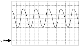
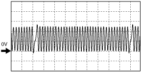
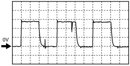
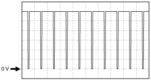
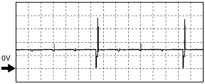
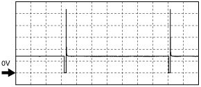
Inspection Using An Oscilloscope (Reference)
Input/turbine speed sensor (+) signal
atraaw00002426
|
Input/turbine speed sensor (-) signal
atraaw00002427
|
A/F sensor heater control
atraaw00002428
|
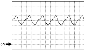
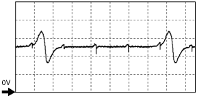
CKP sensor signal
atraaw00002429
|
CMP sensor signal
atraaw00002430
|
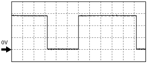
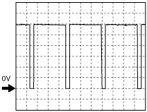
OCV control signal
atraaw00002431
|
Generator output voltage signal
atraaw00002432
|
Generator field coil control signal
atraaw00002433
|
Purge control signal
atraaw00002434
|
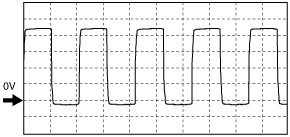
IGT1, IGT2, IGT3, IGT4 control signals
atraaw00002435
|
Fuel injection control
atraaw00002436
|