 |
atraaw00000075
PID/DATA MONITOR INSPECTION[GF4AX-EL]
id0502a2805600
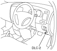
1. Connect the M-MDS to the DLC-2.
atraaw00000075
|
2. After the vehicle is identified, select the following items from the initial screen of the M-MDS.
3. Select the PID from the PID table.
4. Verify the PID data according to the directions on the screen.
PID/DATA MONITOR AND RECORD function table
|
Monitor item (Definition) |
Unit/Condition |
Condition/Specification |
Action |
PCM terminal |
|---|---|---|---|---|
|
GEAR
|
1/2/3/4
|
• 1GR: 1
• 2GR: 2
• 3GR: 3
• 4GR: 4
|
Inspect the following PIDs:
APP, SOL 12S, SOL 23S, SOL 32T, SOL 34S, TRD, TRL, TRS, TSS
|
–
|
|
HTM_CNT
|
–
|
Indicates number of high oil temperature mode (ATF temperature at 130 °C {266 °F} or more) operations
• 0—65,535
|
–
|
–
|
|
HTM_DIS
|
km
|
Indicates travel distance after operation of high oil temperature mode (ATF temperature at 130 °C {266 °F} or more)
• 0—65,535
|
–
|
–
|
|
LINEDES
|
Pa
|
Indicates target line pressure
|
Inspect the following PIDs:
APP, TFT, TFTV, TR, TRD, TRL, TRS, TSS, VSS
|
–
|
|
LPS
(Pressure control solenoid)
|
%
|
• Ignition switch ON: 0%
• Idle: 0—100%
|
• Inspect the following PIDs:
APP, TFTV, TRD, TRL, TRS, TSS
• Inspect the solenoid valve.
|
1B
|
|
SOL 12S
(Shift solenoid A)
|
On/Off
|
• 1GR: Off
• 2GR: On
• 3GR: On
• 4GR: On
|
• Inspect the following PIDs:
APP, GEAR, TRD, TRL, TRS, TSS
• Inspect the solenoid valve.
|
1E
|
|
SOL 23S
(Shift solenoid B)
|
On/Off
|
• 1GR: On
• 2GR: On
• 3GR: Off
• 4GR: Off
|
• Inspect the following PIDs:
APP, GEAR, TRD, TRL, TRS, TSS
• Inspect the solenoid valve.
|
1F
|
|
SOL 32T
(3-2 timing solenoid vale)
|
On/Off
|
• Idle: Off
• When shifting
1-2, 2-3, 3-4, 3-2, or 2-1: On
|
• Inspect the following PIDs:
APP, TRD, TRL, TRS, TSS
• Inspect the solenoid valve.
|
1C
|
|
SOL 34S
(Shift solenoid C)
|
On/Off
|
• 1GR (D range): On
• 1GR (1 range): Off
• 2GR (D range): On
• 2GR (2 range): Off
• 3GR: Off
• 4GR: On
|
• Inspect the following PIDs:
APP, GEAR, TRD, TRL, TRS, TSS
• Inspect the solenoid valve.
|
1G
|
|
SOL TCC
(TCC control solenoid valve)
|
On/Off
|
• TCC control solenoid valve operation: On
• TCC control solenoid valve not operation: Off
|
• Inspect the following PIDs:
APP, TRD, TRL, TRS, TSS
• Inspect the solenoid valve.
|
1H
|
|
TCIL
(O/D OFF indicator light)
|
On/Off
|
• O/D OFF mode: On
• Others: Off
|
Inspect the O/D OFF indicator light.
|
–
|
|
TCS
(O/D OFF switch)
|
On/Off
|
• O/D OFF switch on: On
• O/D OFF switch off: Off
|
Inspect the O/D OFF switch.
|
1O
|
|
TFT
(Transaxle fluid temperature)
|
°C
|
Indicates transaxle fluid temperature
|
Inspect the TFT sensor.
|
1U, 1AE
|
|
TFTV
(Transaxle fluid signal voltage)
|
V
|
• ATF 20 °C {68 °F}: 3—4 V
• ATF 130 °C {266 °F}: 0.2—0.7 V
|
Inspect the TFT sensor.
|
1U, 1AE
|
|
TR
(Transaxle range)
|
P/R/N/D/S/L
|
• P position: P
• R position: R
• N position: N
• D range: D
• 2 range: S
• 1 range: L
|
Inspect the TR switch.
|
1J, 1K, 1L, 1N, 1P, 1S
|
|
TRD
(TR switch
[D range])
|
On/Off
|
• D range: On
• Other: Off
|
Inspect the TR switch.
|
1L
|
|
TRL
(TR switch
[1 range])
|
On/Off
|
• 1 range: On
• Other: Off
|
Inspect the TR switch.
|
1K
|
|
TRN
(TR switch
[N position])
|
On/Off
|
• N position: On
• Other: Off
|
Inspect the TR switch.
|
1S
|
|
TRP
(TR switch
[P position])
|
On/Off
|
• P position: On
• Other: Off
|
Inspect the TR switch.
|
1N
|
|
TRR
(TR switch
[R position])
|
On/Off
|
• R position: On
• Other: Off
|
Inspect the TR switch.
|
1J
|
|
TRS
(TR switch
[2 range])
|
On/Off
|
• 2 range: On
• Other: Off
|
Inspect the TR switch.
|
1P
|
|
TSS
(Input/turbine speed)
|
RPM
|
• Ignition switch ON: 0 RPM
• Idle: 650—750 RPM (P, N position)
Indicates input/turbine speed
|
Inspect the input/turbine speed sensor.
|
1M, 1Q
|
Simulation Function Procedure
1. Connect the M-MDS to the DLC-2.
atraaw00000075
|
2. After the vehicle is identified, select the following items from the initial screen of the M-MDS.
3. Select the simulation items from the PID table.
4. Perform the simulation function, inspect the operations for each parts.
Simulation item table
|
Simulation item |
Applicable component |
Unit/Condition |
Operation |
PCM terminal |
|
|---|---|---|---|---|---|
|
IG ON |
Idle |
||||
|
LPS
|
Pressure control solenoid valve
|
%
|
N/A
|
X
|
1B
|
|
SOL 12S
|
Shift solenoid A
|
On/Off
|
N/A
|
X
|
1E
|
|
SOL 23S
|
Shift solenoid B
|
On/Off
|
N/A
|
X
|
1F
|
|
SOL 32T
|
3-2 timing solenoid valve
|
On/Off
|
N/A
|
X
|
1C
|
|
SOL 34S
|
Shift solenoid C
|
On/Off
|
N/A
|
X
|
1G
|
|
SOL TCC
|
TCC control solenoid valve
|
On/Off
|
N/A
|
X
|
1H
|