 |
atraaw00003345
REAR DRIVE SHAFT DISASSEMBLY/ASSEMBLY
id031300800700
Disassembly
1. Remove the rear drive shaft. (See REAR DRIVE SHAFT REMOVAL/INSTALLATION.)
2. Secure the drive shaft in a vice using protective jaw covers.
atraaw00003345
|
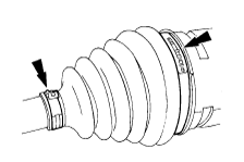
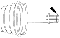
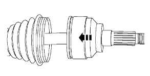
3. Remove the boot band (differential side).
atraaw00003156
|
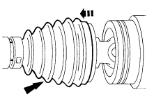
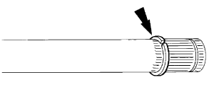
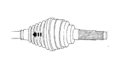
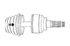
4. Slide and remove the boot.
atraaw00003157
|
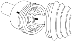
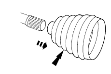
5. If reinstalling the inner joint, mark the inner joint and the drive shaft for correct installation.
atraaw00003346
|
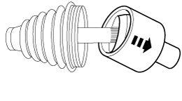
6. Disconnect the drive shaft using a plastic hammer.
atraaw00003142
|
7. Remove and discard the retainer clip.
atraaw00003158
|
8. Remove and discard the snap ring.
atraaw00003159
|
9. Remove the boot from the drive shaft.
atraaw00003160
|
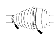
10. Remove the two boot bands (wheel side).
atraaw00003161
|
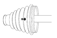
11. Slide the boot back out of the way to expose the joint.
atraaw00003162
|
12. Remove and discard the retainer clip.
atraaw00003158
|
13. Remove the snap ring from the drive shaft.
atraaw00003159
|
14. Slide the remove the boot from the drive shaft.
atraaw00003163
|
Assembly
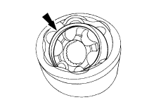
1. Lubricate the joint with grease.
atraaw00003164
|
2. Install the boot (wheel side).
atraaw00003165
|
3. Install the snap ring to the drive shaft.
atraaw00003159
|
4. Install a new retainer clip.
atraaw00003158
|
5. Use a plastic hammer to install the joint (differential side) by gently tapping it onto the drive shaft.
atraaw00003166
|
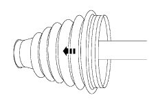
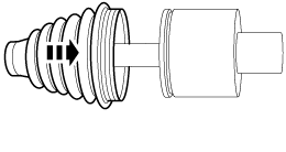
6. Remove any excess grease on the mating surfaces and slide the boot (wheel side) forward onto the joint.
atraaw00003167
|
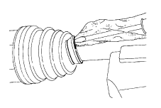
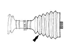
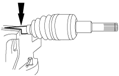
7. Remove any excess air trapped in the boot using a cloth covered screwdriver after installing the boot correctly.
atraaw00003168
|
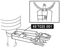
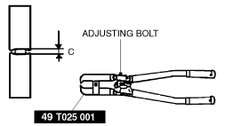
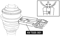
8. Assemble a new boot band.
atraaw00002616
|
acxuuw00001252
|
atraaw00003134
|
atraaw00003135
|
9. Position the boot (differential side).
atraaw00003169
|
10. Install the snap ring.
atraaw00003159
|
11. Install the retainer clip.
atraaw00003158
|
12. Position the boot (wheel side).
atraaw00003155
|
13. Remove any excess air trapped in the boot using a cloth covered screwdriver after installing the boot correctly.
atraaw00003168
|
14. Follow the same procedures to install the two new boot bands on the opposite side.
15. Install the rear drive shaft. (See REAR DRIVE SHAFT REMOVAL/INSTALLATION.)