 |
atraaw00001363
PRECAUTION[AJ (3.0L Duratec)]
id0403b1804100
Inspection/Verification
1. Verify the customer concern by applying the brakes under different conditions.
2. Visually inspect for obvious signs of mechanical and electrical malfunction.
3. If the cause of malfunction is not detected by visual inspection, connect the M-MDS, and perform DTC inspection.
4. If any DTC related to the malfunction is read, refer to the DTC TABLE and continue malfunction diagnosis. (See ON-BOARD DIAGNOSIS[AJ (3.0L Duratec)].)
5. If any DTC related to the malfunction is not read, refer to the “SYMPTOM TROUBLESHOOTING CHART” and continue malfunction diagnosis. (See SYMPTOM TROUBLESHOOTING[AJ (3.0L Duratec)].)
Intermittent Concern Troubleshooting
Vibration method
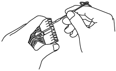
Inspection method for switch connectors or wiring harnesses
1. Connect the M-MDS to the DLC-2.
2. Turn the ignition switch to the ON position (Engine OFF).
3. Access PIDs for the switch you are inspecting.
4. Turn the switch on manually.
5. Slightly shake each connector or wiring harness vertically and horizontally while monitoring the PID.
atraaw00001363
|
Inspection method for sensor connectors or wiring harnesses
1. Connect the M-MDS to the DLC-2.
2. Turn the ignition switch to the ON position (Engine OFF).
3. Access PIDs for the switch you are inspecting.
4. Slightly shake each connector or wiring harness vertically and horizontally while monitoring the PID.
atraaw00001364
|
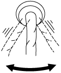
Inspection method for sensors
1. Connect the M-MDS to the DLC-2.
2. Turn the ignition switch to the ON position (Engine OFF).
3. Access PIDs for the switch you are inspecting.
4. Vibrate the sensor slightly with your finger.
Malfunction data monitor method
1. Perform malfunction reappearance test according to malfunction reappearance mode and malfunction data monitor. The malfunction cause is found in the malfunction data.
Connector terminal inspection method
1. Inspect the connection of each female terminal.
2. Insert the male terminal to the female terminal and Inspect the female terminal for looseness.
atraaw00001365
|