 |
atraaw00001357
ON-BOARD DIAGNOSIS[AJ (3.0L Duratec)]
id040242805500
On-Board Diagnostic (OBD) Test Description
Read/clear diagnostic results
PID/Data monitor and record
Active command modes
Reading DTCs Procedure
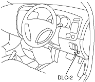
1. Connect the M-MDS to the DLC‐2 connector.
atraaw00001357
|
2. After the vehicle is identified, select the following items from the initial screen of the M-MDS.
3. Verify the DTC according to the directions on the screen.
4. After completion of repairs, clear all DTCs stored in the ABS. (See ON-BOARD DIAGNOSIS[AJ (3.0L Duratec)].)
Clearing DTCs Procedures
1. Connect the M-MDS to the DLC‐2 connector.
atraaw00001357
|
2. After the vehicle is identified, select the following items from the initial screen of the M-MDS.
3. Verify the DTC according to the directions on the screen.
4. Press the clear button on the DTC screen to clear the DTC.
5. Verify that no DTCs are displayed.
PID/Data Monitor and Record Procedure
1. Connect the M-MDS to the DLC‐2 connector.
atraaw00001357
|
2. After the vehicle is identified, select the following items from the initial screen of the M-MDS.
3. Select the applicable PID from the PID table.
4. Verify the PID data according to the directions on the screen.
Active Command Modes Procedure
1. Connect the M-MDS to the DLC‐2 connector.
atraaw00001357
|
2. After the vehicle is identified, select the following items from the initial screen of the M-MDS.
3. Select the active command modes from the PID table.
4. Perform the active command modes, inspect the operations for each parts.
DTC Table
|
DTC |
System Malfunction Location |
Page |
|---|---|---|
|
M-MDS display |
||
|
B1342
|
ABS HU/CM
|
(See DTC B1342[AJ (3.0L Duratec)].)
|
|
B1676
|
Battery voltage
|
(See DTC B1676[AJ (3.0L Duratec)].)
|
|
C1095
|
Pump motor
|
(See DTC C1095[AJ (3.0L Duratec)].)
|
|
C1145
|
RF ABS wheel-speed sensor
|
|
|
C1155
|
LF ABS wheel-speed sensor
|
|
|
C1165
|
RR ABS wheel-speed sensor
|
|
|
C1175
|
LR ABS wheel-speed sensor
|
|
|
C1233
|
LF ABS sensor rotor
|
|
|
C1234
|
RF ABS sensor rotor
|
|
|
C1235
|
RR ABS sensor rotor
|
|
|
C1236
|
LR ABS sensor rotor
|
PID/DATA Monitor Table
|
PID name (definition) |
Unit/Operation |
Operation condition (Reference) |
Action |
ABS HU/CM terminal |
|---|---|---|---|---|
|
M-MDS display |
||||
|
BOO_ABS
|
On/Off
|
• Brake pedal depressed: On
• Brake pedal released: Off
|
• Inspect the brake switch.
|
—
|
|
CCNTABS
|
-
|
Indicates number of DTC
|
• Perform the DTC inspection.
|
—
|
|
G_INPUT
|
G
|
• Vehicle stopped or driving at constant speed: 0 G
• Accelerated: Changes 0 G—positive
• Decelerated: Changes 0 G—negative
|
• Inspect the ABS HU/CM.
|
—
|
|
LF_WSPD
|
KPH, MPH
|
• Vehicle stopped: 0 KPH, 0 MPH
• Vehicle running: Vehicle speed
|
• Inspect the ABS wheel-speed sensor.
|
U, X
|
|
LR_WSPD
|
KPH, MPH
|
• Vehicle stopped: 0 KPH, 0 MPH
• Vehicle running: Vehicle speed
|
• Inspect the ABS wheel-speed sensor.
|
I, L
|
|
RF_WSPD
|
KPH, MPH
|
• Vehicle stopped: 0 KPH, 0 MPH
• Vehicle running: Vehicle speed
|
• Inspect the ABS wheel-speed sensor.
|
P, S
|
|
RR_WSPD
|
KPH, MPH
|
• Vehicle stopped: 0 KPH, 0 MPH
• Vehicle running: Vehicle speed
|
• Inspect the ABS wheel-speed sensor.
|
J, G
|
Active Command Modes Table
|
Command name |
Output device |
Operation |
Operating condition |
|---|---|---|---|
|
G_SENSOR
|
G-sensor
|
On/Off
|
Ignition switch at ON
|
|
LF_INLET
|
LF inlet solenoid valve
|
||
|
LF_OUTLET
|
LF outlet solenoid valve
|
||
|
LR_INLET
|
LR inlet solenoid valve
|
||
|
LR_OUTLET
|
LR outlet solenoid valve
|
||
|
PMP_MOTOR
|
Pump motor
|
||
|
RF_INLET
|
RF inlet solenoid valve
|
||
|
RF_OUTLET
|
RF outlet solenoid valve
|
||
|
RR_INLET
|
RR inlet solenoid valve
|
||
|
RR_OUTLET
|
RR outlet solenoid valve
|