 |
atraaw00003104
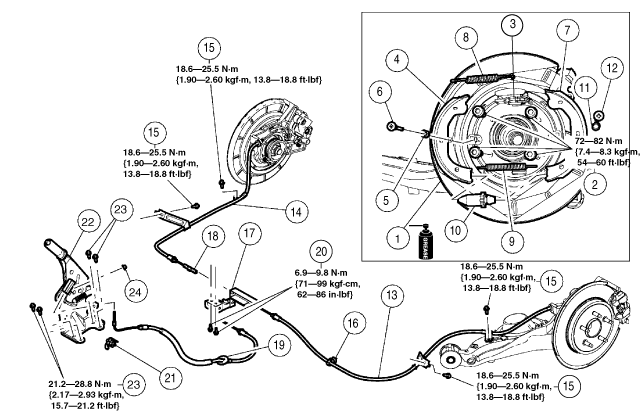
PARKING BRAKE LEVER INSTALLATION
id041200801000
1. Install in the order indicated in the table.
2. Install the disc plate and the brake caliper component. (See REAR BRAKE (DISC) REMOVAL/INSTALLATION.)
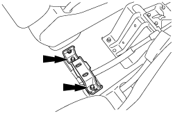
3. Install the floor console bracket.
atraaw00003104
|
4. Install the floor console. (See FLOOR CONSOLE REMOVAL/INSTALLATION.)
5. Install the rear wheel and tire assembly.
atraaw00001967
|
|
1
|
Back plate
|
|
2
|
Bolt
|
|
3
|
Operating lever
|
|
4
|
Leading shoe
|
|
5
|
Hold spring (leading shoe side)
|
|
6
|
Hold pin (leading shoe side)
|
|
7
|
Trailing shoe
|
|
8
|
Return spring (upper)
|
|
9
|
Return spring (lower)
|
|
10
|
Adjuster
|
|
11
|
Hold spring (trailing shoe side)
|
|
12
|
Hold pin (trailing shoe side)
|
|
13
|
Rear parking brake cable (LH)
|
|
14
|
Rear parking brake cable (RH)
|
|
15
|
Bolt
|
|
16
|
Clip
|
|
17
|
Equalizer
|
|
18
|
Cable connector
|
|
19
|
Front parking brake cable
|
|
20
|
Bolt
|
|
21
|
Parking brake switch
|
|
22
|
Parking brake lever
|
|
23
|
Bolt
|
|
24
|
Adjusting nut
|
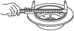
Adjusting Nut Installation Note
1. Using the vernier caliper, measure the inside diameter of the drum portion of the rear brake disc.
atraaw00001968
|
2. Place the vernier caliper over the widest diameter of the parking brake shoes.
3. Turn the parking brake control adjustment nut to adjust the parking brake control stroke.
4. Verify the parking brake is applied.