|
atraaw00001985
TRANSAXLE RANGE (TR) SWITCH REMOVAL/INSTALLATION[GF4AX-EL]
id051703804000
1. Disconnect the negative battery cable.
2. Remove the battery and battery tray.
3. Disconnect the TR switch connector.
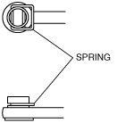
4. Remove the spring and disconnect the selector cable.
atraaw00001985
|
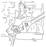
5. Set the adjustable wrench as shown in the figure to hold the manual shaft lever.
atraaw00001988
|
6. Remove the manual shaft nut and washer.
7. Remove the manual shaft lever.
8. Remove the TR switch.
9. Rotate the manual shaft to the rear side of the vehicle fully, then return 2 notches to set the N position.
atraaw00001989
|
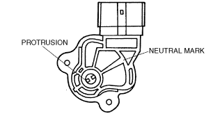
10. Align the protrusion and neutral mark as shown in the figure.
atraaw00001990
|
11. Install the TR switch while aligning the protrusion and groove as shown in the figure.
atraaw00001991
|
12. Turn the TR switch so that the neutral mark is in line with the flat, straight surfaces on either side of the manual shaft.
atraaw00001992
|
13. Hand-tighten the TR switch bolts.
14. Verify that the continuity between the terminals B and H.
atraaw00001987
|
15. Tighten the TR switch mounting bolts.
16. Install the manual shaft lever and washer.
17. Set the adjustable wrench as shown in the figure to hold the manual shaft lever.
18. Tighten the manual shaft nut using a torque wrench.
atraaw00001993
|
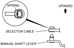
19. Install the spring as shown in the figure.
atraaw00000867
|
20. Verify that the selector lever range position and TR switch are aligned, then connect the selector cable.
atraaw00000868
|
21. Inspect for continuity at the TR switch. (See TRANSAXLE RANGE (TR) SWITCH INSPECTION[GF4AX-EL].)
22. Connect the TR switch connector.
23. Install the battery tray and battery.
24. Connect the negative battery cable.
25. Inspect operation of the TR switch. (See TRANSAXLE RANGE (TR) SWITCH INSPECTION[GF4AX-EL].)