 |
atraaw00001820
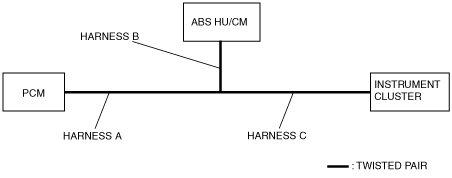
PROCEDURES FOR DETERMINING LOCATION OF MALFUNCTION[MULTIPLEX COMMUNICATION SYSTEM (L3)]
id0902h5825700
System Wiring Diagram
atraaw00001820
|
PCM
1. Using the M-MDS, verify that the DTC U0121 is displayed. (See DTC TABLE[MULTIPLEX COMMUNICATION SYSTEM (L3)].)
2. Referring to the following table, determine the malfunctioning part of the CAN system.
|
Module |
Communication status |
Malfunctioning part |
|
|---|---|---|---|
|
ABS HU/CM |
Instrument cluster |
||
|
PCM
|
Error
|
Error
|
• Wiring harness A
• PCM
|
|
Error
|
Normal
|
• Wiring harness B
• ABS HU/CM
|
|
|
Normal
|
Error
|
• Wiring harness C
• Instrument cluster
|
|
Instrument cluster
1. Using the M-MDS, verify that DTC U1900 is displayed. (See DTC TABLE[MULTIPLEX COMMUNICATION SYSTEM (L3)].)
2. Access and monitor the “PCM_MSG” and “ABS_MSG” PIDs using the M-MDS.
3. Verify the PID. (See PID/DATA MONITOR AND RECORD PROCEDURE[L3].)
4. Referring to the following table, determine the malfunctioning part of the CAN system.
|
Module |
Communication status |
Malfunctioning part |
|
|---|---|---|---|
|
PCM |
ABS HU/CM |
||
|
Instrument cluster
|
Error
|
Error
|
• Wiring harness C
• Instrument cluster
|
|
Error
|
Normal
|
• Wiring harness A
• PCM
|
|
|
Normal
|
Error
|
• Wiring harness B
• ABS HU/CM
|
|
ABS HU/CM
1. Using the M-MDS, verify that DTC U1900 or U2023 is displayed. (See DTC TABLE[MULTIPLEX COMMUNICATION SYSTEM (L3)].)
2. Referring to the following table, determine the malfunctioning part of the CAN system.
|
Module |
Communication status |
Malfunction location |
|
|---|---|---|---|
|
PCM
|
Instrument cluster |
||
|
ABS HU/CM
|
Error
|
Error
|
• Wiring harness B
• ABS HU/CM
|
|
Error
|
Normal
|
• Wiring harness A
• PCM
|
|
|
Normal
|
Error
|
• Wiring harness C
• Instrument cluster
|
|