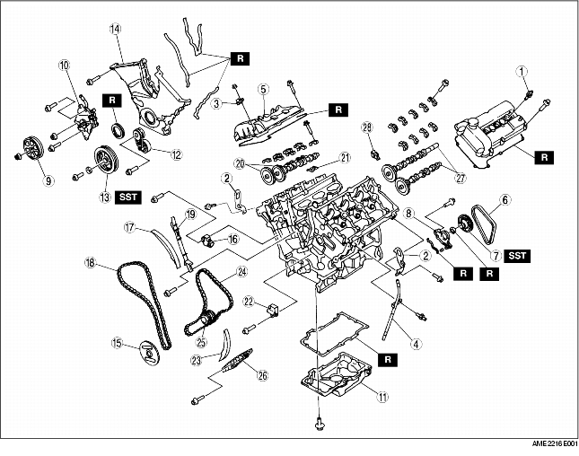
1. Disassemble in the order indicated in the table.
|
1
|
Spark plug
|
|
2
|
Engine hanger
|
|
3
|
Condenser
|
|
4
|
Oil level gauge, pipe
|
|
5
|
Cylinder head cover
|
|
6
|
Water pump drive belt
|
|
7
|
Water pump drive pulley
|
|
8
|
Camshaft oil seal housing
|
|
9
|
P/S oil pump pulley
|
|
10
|
P/S oil pump
|
|
11
|
Oil pan
(See Oil Pan Disassembly Note)
|
|
12
|
Auto tensioner
|
|
13
|
Crankshaft pulley
|
|
14
|
Engine front cover
|
|
15
|
CKP sensor pulse wheel
|
|
16
|
Chain tensioner (RH)
|
|
17
|
Tensioner arm (RH)
|
|
18
|
Timing chain (RH)
|
|
19
|
Chain guide (RH)
|
|
20
|
Camshaft (RH)
|
|
21
|
Rocker arm (RH)
|
|
22
|
Chain tensioner (LH)
|
|
23
|
Tensioner arm (LH)
|
|
24
|
Timing chain (LH)
|
|
25
|
Crankshaft timing sprocket (LH)
|
|
26
|
Chain guide (LH)
|
|
27
|
Camshaft (LH)
|
|
28
|
Rocker arm (LH)
|
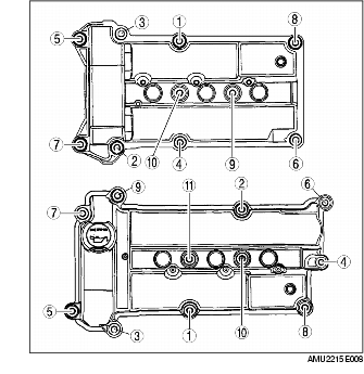
1. Remove the cylinder head cover bolts in the order indicated in the figure.
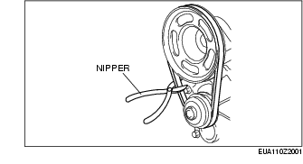
1. Rotate the belt tensioner clockwise to release the drive belt tension and remove the belt.
1. Cut the belt using scissors or nipper as indicated in the figure.
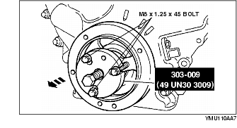
1. Replace part A of the SST [303-009 (49 UN30 3009)] with the SST [303-457 (49 UN30 3457)].
2. Remove the water pump pulley using the SST.
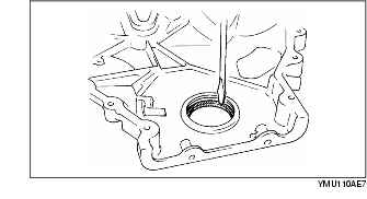
1. Remove the oil seal using a screwdriver.
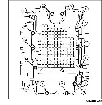
1. Remove the oil pan bolts and studs in the order indicated in the figure.
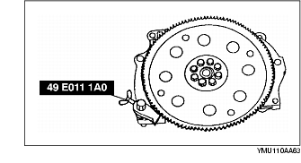
1. Hold the crankshaft using the SST.
2. Remove the crankshaft pulley lock bolt.
3. Remove the crankshaft pulley using the SST and three bolts (M8 x 1.25 x 45).
1. Remove the engine front cover bolts and studs in the order indicated in the figure.
2. Remove the oil seal using a screwdriver.
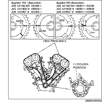
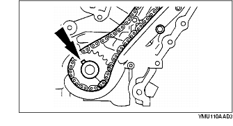
1. Before removing chain tensioner (RH), turn the crankshaft clockwise to position the crankshaft keyway in the 11 o'clock position.
2. Verify that marks on the camshaft sprockets are aligned.
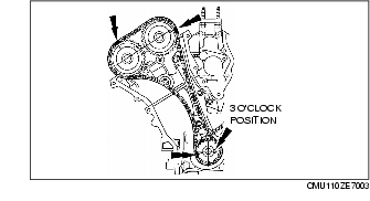
3. Turn the crankshaft clockwise to position the crankshaft keyway in the 3 o'clock position. (camshafts (RH) are in the neutral position.)
4. Place alignment marks on the timing chain corresponding to each of the alignment marks on the timing sprocket.
5. Hold the timing chain tensioner ratchet lock mechanism away from the ratchet stem with a thin screwdriver.
6. Slowly press the tensioner piston.
7. Hold the tensioner piston with a 1.5 mm {0.06 in} wire or paper clip.
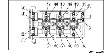
1. Before removing the camshaft, inspect the following.
2. Remove the camshaft cap bolts in the order indicated in the figure in several passes.
1. Before removing chain tensioner (LH), turn the crankshaft clockwise 1 and 2/3 turns to position the crankshaft keyway in the 11 o'clock position. (camshafts (LH) are in the neutral position.)
2. Place alignment marks on the timing chain corresponding to each of the alignment marks on the timing sprocket.
3. Press and hold the tensioner piston by following Step 4 to 6 in Chain Tensioner (RH) Disassembly Note. (See Chain Tensioner (RH) Disassembly Note.)
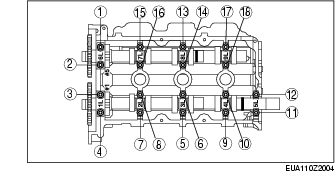
1. Before removing the camshaft, inspect the following.
2. Remove the camshaft cap bolts in the order indicated in the figure in several passes.
Water pump drive pulley on intake camshaft side
Water pump drive pulley on exhaust camshaft side