1. Assemble in the order indicated in the table.
|
1
|
Clutch housing
(See Clutch Housing Assembly Note.)
|
|
2
|
Transfer
|
|
3
|
Differential component
|
|
4
|
Shift gate
|
|
5
|
1st/2nd shift rod
|
|
6
|
1st/2nd shift fork
|
|
7
|
1st/2nd shift end
|
|
8
|
1st/2nd shift fork component
|
|
9
|
3rd/4th shift rod
|
|
10
|
3rd/4th shift fork
|
|
11
|
3rd/4th shift fork component
|
|
12
|
Secondary shaft gear component
|
|
13
|
Primary shaft gear component
|
|
14
|
Shift rod
|
|
15
|
Shift rod end
|
|
16
|
Shift rod component
|
|
17
|
Reverse idler shaft
|
|
18
|
Reverse idler gear support
|
|
19
|
Reverse idler gear
|
|
20
|
Reverse idler shaft
|
|
21
|
Oil passage
|
|
22
|
Transaxle case component
|
|
23
|
Back-up light switch
|
|
24
|
Transaxle hanger
|
|
25
|
Spring, steel ball
|
|
26
|
Top cover component
(See Top Cover Assembly Note.)
|
|
27
|
Inter lock pin
|
|
28
|
Inter lock plate
|
|
29
|
Secondary 5th gear
|
|
30
|
Gear sleeve
|
|
31
|
5th gear
|
|
32
|
Synchronizer lever
|
|
33
|
5th synchronizer ring
|
|
34
|
Clutch hub
|
|
35
|
Clutch hub sleeve
|
|
36
|
Synchronizer key springs
|
|
37
|
5th/reverse clutch hub component
|
|
38
|
5th/reverse shift fork
|
|
39
|
Locknut (secondary shaft)
(See Locknut Assembly Note.)
|
|
40
|
Locknut (primary shaft)
(See Locknut Assembly Note.)
|
|
41
|
Rear cover
|
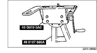
1. Assemble the SST.
2. Assembly clutch housing on the SST.
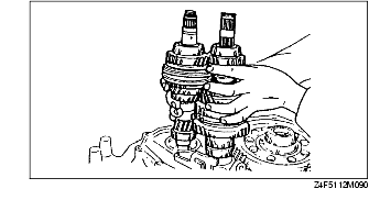
1. Install the primary shaft gear component and the secondary shaft gear component together.
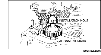
1. Align the installation hole of the reverse idle gear support lock bolt with the clutch housing alignment mark.
2. Verify that the reverse shift lever and reverse idle gear sleeve are engaged.
1. Apply a thin coat of sealant to the contact surfaces of the clutch housing and transaxle case, and tighten the transaxle case installation bolts to the specified torque.
2. Install the SSTs through the drive shaft and joint shaft hole.
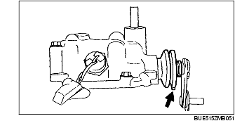
1. Remove the top cover.
2. Verify that the boot water drain hole is positioned as shown in the figure.
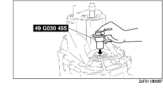
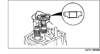
1. Install the secondary 5th gear as shown in the figure.
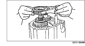
1. Install the 5th/reverse clutch hub component and the 5th/reverse shift fork together.
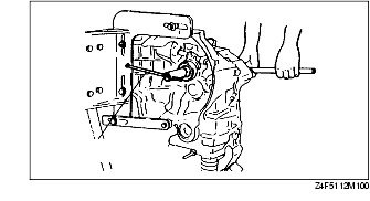
1. Shift to 1st gear.
2. Lock the primary shaft using the SST.
3. Tighten new lock nuts onto the primary and secondary shafts.
4. Stake the locknuts.
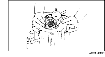
5. Measure the 5th gear thrust clearance using a dial indicator.