GENERATOR CONSTRUCTION [L3]
BUE011718300N01
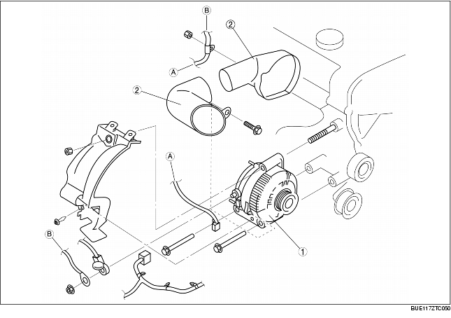
L.H.D.
• The regulator has been integrated in the generator.
• A generator duct have been adopted to protect the generator from the exhaust manifold heat.
|
1
|
Generator
|
|
2
|
Generator duct
|
|
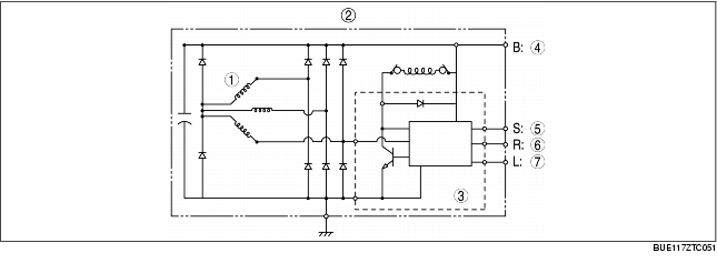
1
|
Stator coil
|
|
2
|
Generator
|
|
3
|
Regulator
|
|
4
|
Battery voltage
|
|
5
|
Battery sense
|
|
6
|
Regulator control
|
|
7
|
Load indicator
|
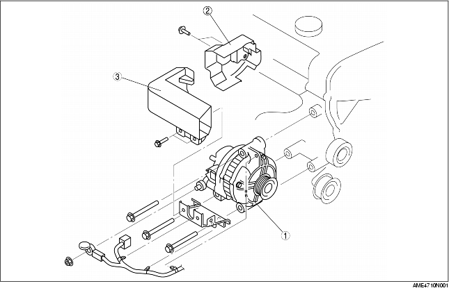
R.H.D.
• The interior construction of the generator has been simplified by the elimination of the IC regulator based on the PCM performing generator output control.
• A generator duct and a generator heat insulator made of plastic have been adopted to protect the generator from the exhaust manifold heat.
|
1
|
Generator
|
|
2
|
Generator heat insulator
|
|
3
|
Generator duct
|
|
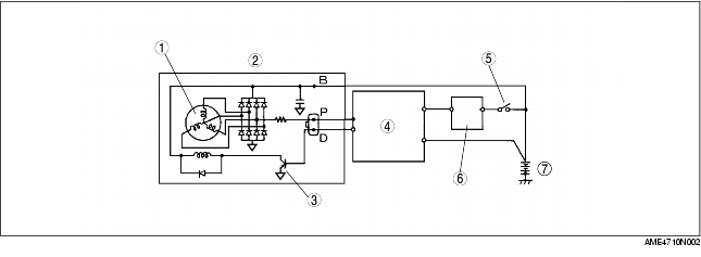
1
|
Stator coil
|
|
2
|
Generator
|
|
3
|
Power transistor
|
|
4
|
PCM
|
|
5
|
Ignition switch
|
|
6
|
Generator warning light
|
|
7
|
Battery
|
-
- Generator B terminal signal malfunction
-
- Generator output voltage signal malfunction
-
- Battery over-charge
-
- Intake air temperature sensor (PCM input voltage too low)
-
- Intake air temperature sensor (PCM input voltage too high)