MULTIPLEX COMMUNICATION SYSTEM CONSTRUCTION/OPERATION [L3]
BUE094055430N05
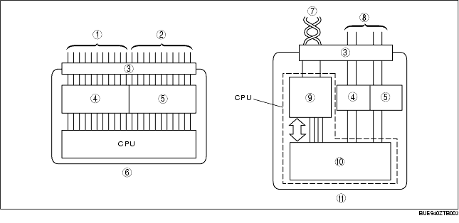
CAN System-Related Module Construction
• A CAN system-related module is composed of a power circuit, CPU, and input/output interface.
• Module size has been reduced due to the elimination of redundant parts of the input/output interface used in conventional types of electronic modules.
• The CPU (multiplex block) controls all signals exchanged via the bus lines (multiplex communication system wiring harnesses).
• Communication with non-multiplex parts is carried out using conventional input/output interface.
• The functions of each component are shown below.
|
Component
|
Function
|
|
Power circuit
|
Supplies power to CPU and vicinity, and to input/output interface.
|
|
CPU
|
Computation processing block
|
In addition to conventional CPU function, when transmission is necessary, transmitted data is stored in a multiplex block.
When the multiplex block receives a request to read stored data, transmitted data is read from the multiplex block.
|
|
Multiplex block
|
Transmits data received from bus lines to computation processing block.
In addition, sends transmitted data stored from computation processing block to bus lines.
|
|
Input interface circuit
|
Converts information signals from switches to electrical signals that can be input to CPU.
|
|
Output interface circuit
|
Converts electrical signals output from CPU for operating motors and other parts.
|
|
1
|
Input signal
|
|
2
|
Output signal
|
|
3
|
Connector
|
|
4
|
Input interface
|
|
5
|
Output interface
|
|
6
|
Conventional module
|
|
7
|
CAN harness (twisted pair)
|
|
8
|
Conventional wiring harness
|
|
9
|
Multiplex block
|
|
10
|
Computation processing block
|
|
11
|
CAN system-related module
|
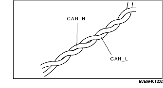
Twisted Pair Construction
• The CAN system uses two spirally twisted wires called a twisted pair, and each wire, bus line A (CAN_L) and bus line B (CAN_H), has unique characteristics.
• Both bus lines are opposite phase voltage so that emitted noise is lessened and exterior noise interference is not easily received.
CAN System Outline
• For information exchange between electronic modules in a conventional system, separate information signals are required. However, with the CAN system, it is possible to send a large amount of information via a small wiring harness by sending multiple signals at varying times over one channel. This is referred to as time division multiplexing.
CAN System Operation
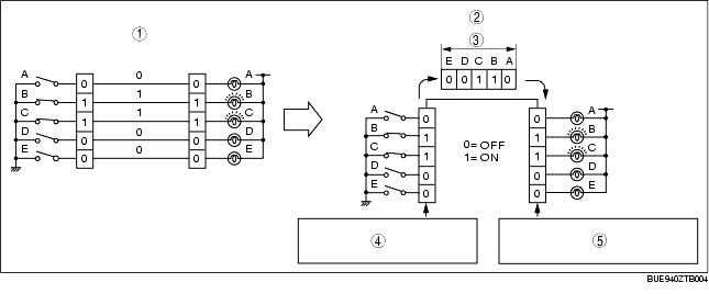
Time Division Multiplex
-
• In the conventional, non-multiplex system, in order to control the illumination of the five bulbs, one switch and one channel was necessary for each bulb. For bulbs B and C to illuminate, switches B and C must be connected and electricity must flow through each transmission channel.
-
• With the time multiplex system, this can be done through a single wire. The channel is comprised of five data signal transmitters which transmit either a "0" or "1" signal to indicate whether a bulb turns ON or OFF. For example, to illuminate bulbs B and C, transmitters B and C transmit a "1" and transmitters A, D, and E transmit a "0". When the receiver receives these signal, bulbs B and C are illuminated.
|
1
|
Non-multiplex system
|
|
2
|
Time division multiplex system
|
|
3
|
Data
|
|
4
|
Each signal is transmitted one by one through the channel as it is received.
|
|
5
|
Each signal is output one by one as it is received from the channel.
|
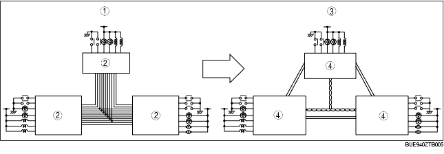
Vehicle CAN System
-
• By rearranging the multiple signal, common information between the electronic modules is transmitted and received via the twisted pairs.
-
• The signal transmitted by one CAN system-related module is sent via twisted pairs to all the CAN system-related modules, but only the corresponding module(s) receives the signal and performs the appropriate operation.
|
1
|
Conventional system
|
|
2
|
Electrical module
|
|
3
|
CAN system
|
|
4
|
CAN system-related module
|
CAN Signal Table
• Sending/receiving of CAN signals is as follows:
OUT: Output (Sends signal)
IN: Input (Receives signal)
|
Signal
|
CAN system-related module
|
|
PCM
|
ABS HU/CM
|
Instrument cluster
|
|
Engine speed
|
OUT
|
-
|
IN
|
|
Vehicle speed
|
OUT
|
-
|
IN
|
|
Brake system warning light illumination request
|
-
|
OUT
|
IN
|
|
ABS warning light illumination request
|
-
|
OUT
|
IN
|
|
ECT
|
OUT
|
-
|
IN
|
|
Distance travelled
|
OUT
|
-
|
IN
|
|
Engine warning light illumination request
|
OUT
|
-
|
IN
|
|
O/D OFF indicator light illumination request
|
OUT
|
-
|
IN
|
|
Generator warning light illumination request
|
OUT
|
-
|
IN
|
|
Wheel speed (LF, RF, LR, RR)
|
IN
|
OUT
|
-
|
|
Engine specification
|
OUT
|
IN
|
-
|
ON-BOARD DIAGNOSTIC SYSTEM OUTLINE
• CAN system-related modules have an on-board diagnostic function that is able to determine malfunction locations when there is an irregularity in the CAN system.
• The on-board diagnostic function has a malfunction detection function that detects irregularities in CAN system-related parts, a memory function that stores detected malfunctions, and a display function that displays the location and contents of malfunctions via DTC output.
• DTCs can be read out and cleared using the WDS or equivalent.
• The CAN system has a fail-safe function. When a malfunction occurs in the CAN system, the transmission module sends a warning signal, the receiving module illuminates the warning light, and the fail-safe function performs control to safeguard the system.
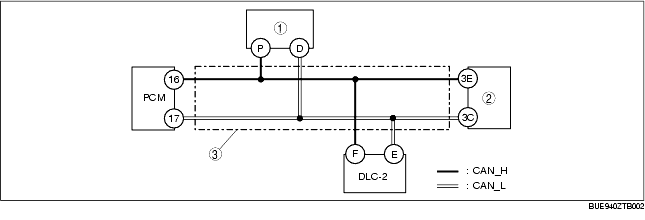
On-Board Diagnostic System Construction/Operation
Block Diagram
|
1
|
ABS HU/CM
|
|
2
|
Instrument cluster
|
|
3
|
Twisted pair
|
Malfunction detection function
-
• Detects irregularities in the input/output signals of CAN system-related modules.
-
• The DTC for the detected malfunction is output to the DLC-2, and the detected result is also sent to the memory, display, and fail-safe functions.
Fail-safe function
-
• When the malfunction detection function determines that there is an irregularity, the fail-safe function illuminates a warning light to advise the driver and controls input and output parts to allow safe driving.
Memory function
-
• Stores DTCs for malfunctions of the input/output signal system, as determined by the malfunction detection function.
Display function
-
• Outputs the signal for a malfunction determined by the malfunction detection function as a DTC to the DLC-2.
-
• DTCs can be read out using the WDS or equivalent.
DTC table
|
DTC
|
Malfunction location
|
DTC Output Unit
|
|
U0073
|
Module communication error
|
• PCM
• Instrument cluster
|
|
U0121
|
Communication error
|
PCM
|
|
U1900
|
Communication error
|
• ABS HU/CM
• Instrument cluster
|
|
U2023
|
Abnormal data
|
ABS HU/CM
|
PID/data monitor function
-
• The PID/data monitor function is used for optionally selecting input/output signal monitor items preset in the instrument cluster and reading them out in real-time.
-
• PIDs can be read out using the WDS or equivalent.
|
WDS or equivalent display
|
Status
|
Description
|
Monitor module
|
Terminal
|
|
ABS_MSG
|
Present
|
Communication circuit between ABS HU/CM and monitor module is normal
|
Instrument cluster
|
3E, 3C
|
|
Not Present
|
Communication circuit between ABS HU/CM and monitor module is not normal
|
|
PCM_MSG
|
Present
|
Communication circuit between PCM and monitor module is normal
|
|
Not Present
|
Communication circuit between PCM and monitor module is not normal
|
Malfunction Location Determination
-
• The on-board diagnostic function can determine CAN system malfunction locations by verifying the detected DTC information from each module.
-
• Refer to the display function for a detailed explanation of DTCs. (See Display function.)
Flowchart
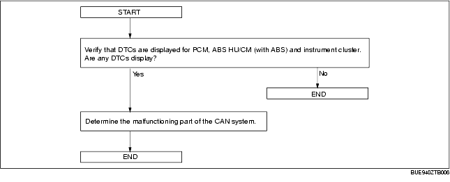
Example (PCM-related wiring harness open circuit)
-
Note
-
• This example applies to the PCM, ABS HU/CM, and instrument cluster.
1. DTCs for CAN system-related modules are verified using the WDS or equivalent.
|
Module
|
DTC
|
Probable malfunction location
|
|
PCM
|
U0073
|
PCM-related CAN system malfunction
|
|
U0121
|
Communication error
|
|
ABS HU/CM
|
U2523
|
Communication error
|
|
Instrument cluster
|
U1900
|
Communication error
|
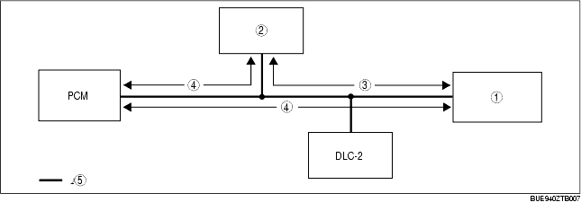
2. Instrument cluster PIDs are verified using the WDS or equivalent.
|
PID
|
DTC
|
Probable malfunction location
|
|
PCM_MSG
|
Not Present
|
Communication error between the instrument cluster and the PCM
|
|
ABS_MSG
|
Present
|
Normal communication between instrument cluster and ABS HU/CM
|
|
1
|
Instrument cluster
|
|
2
|
ABS HU/CM
|
|
3
|
Communication normal
|
|
4
|
Communication error
|
|
5
|
Twisted pair
|
3. If there is a communication error between the instrument cluster and PCM, even if the communication between the DSC HU/CM and the instrument cluster is normal, it is probable that there is a malfunction in the PCM or PCM-related wiring harnesses.