1. Remove the fuel-filler cap.
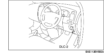
2. Connect the WDS or equivalent to the DLC-2.
3. Operate the fuel pump using the simulation function FP.
4. Verify that there is operation sound from the fuel pump.

1. Disconnect the negative battery cable.
2. Disconnect the fuel pump unit connector.
3. Inspect for continuity between fuel pump unit terminals C-D.
1. Perform the 'Fuel Line Safety Procedure' referring to the BEFORE SERVICE PRECAUTION. (See BEFORE SERVICE PRECAUTION [L3].)
2. Disconnect the negative battery cable.
3. Disconnect the fuel tank side quick release connector of fuel filter (high-pressure). (See FUEL FILTER (HIGH-PRESSURE) REMOVAL/INSTALLATION [L3].)
4. Install the SST. Turn the lever of the SST to the 90× position to the hose to plug the outlet of the SST.
5. Insert the SST quick release connector into the fuel pipe until a click is heard.
6. Verify that the installation is secured by pulling the quick release connector.
7. Prevent fuel spillage by placing the fuel hose outlet (rubber hose) of the SST into a container.
8. Connect the negative battery cable.
9. Connect the WDS or equivalent to the DLC-2.
10. Measure the fuel pump discharge pressure for 10 s during fuel pump operation, using the FP simulation function.
11. Stop the fuel pump operation and measure the fuel pressure after 5 min.
12. Perform the 'Fuel Line Safety Procedure' referring to the BEFORE SERVICE PRECAUTION. (See BEFORE SERVICE PRECAUTION [L3].)
13. Disconnect the SST.
14. Connect the quick release connector. (See QUICK RELEASE CONNECTOR REMOVAL/INSTALLATION [L3].)
15. Inspect all parts by performing the AFTER SERVICE PRECAUTION. (See AFTER SERVICE PRECAUTION [L3].)


