1. Make sure the battery is fully charged. Carry out a battery load test. (See BATTERY INSPECTION [YF (2.0L Zetec)].)
2. Disconnect the ignition coil connector.
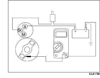
3. Connect a remote starter switch between the starter solenoid S-terminal and the battery positive (+) post.
4. Connect the positive (+) lead of digital multimeter to the battery positive (+) post. Connect the negative (-) lead of the multimeter to the starter solenoid M-terminal.
5. Engage the remote starter switch. Read and record the voltage. The multimeter reading should be 0.5 V or less.
6. If the voltage reading is 0.5 V or less, go to the Starter Motor-Ground Circuit Component Test
7. If the voltage reading is greater than 0.5 V, this is an indication of excessive resistance in the connections, the positive battery cable or in the starter solenoid. Move the digital multimeter negative lead to the starter solenoid B-terminal and repeat the test. If the voltage reading at the B-terminal is lower than 0.5 V, the concern is either in the connections at the starter solenoid or in the solenoid contacts.
8. Remove the cables at the starter solenoid B-, S-, and M-terminals. Clean the connections and install the cables. Repeat Steps 3 through 6 above. If the reading is still higher than 0.5 V at the M-terminal and 0.5 V or lower at the B-terminal, the concern is the solenoid contacts. Install a new starter motor. (See STARTER REMOVAL/INSTALLATION [YF (2.0L Zetec)].)
9. If the voltage measured in Step 5 is greater than 0.5 V, the concern is either the positive (+) battery cable connection or the positive (+) battery cable itself. Clean the positive (+) battery cable connection. If this does not solve the problem, install a new positive battery cable.
1. Disconnect the ignition coil connector.
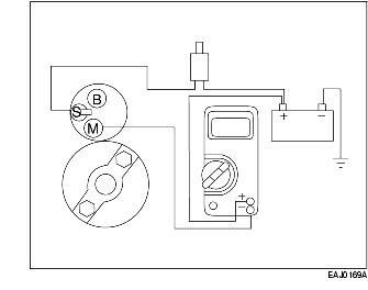
2. Connect a remote starter switch between the starter solenoid S-terminal and the battery positive (+) terminal.
3. Connect the positive (+) lead of digital multimeter to the starter motor housing. The connection must be clean and free of rust or grease. Connect the negative (-) lead to the negative (-) battery terminal.
4. Engage the remote starter switch and read the voltage. The reading should be 0.2 V or less.
5. If the voltage drop is greater than 0.2 V, clean the negative (-) battery cable connections at the battery, the body ground connections, and the starter ground connections. Retest.
6. If the voltage is still more than 0.2 V, install a new cable. If the reading is less than 0.2 V and the engine still cranks slowly, install a new starter motor.
1. Remove the starter motor. (See STARTER REMOVAL/INSTALLATION [YF (2.0L Zetec)].)
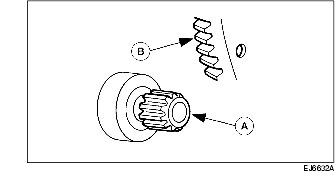
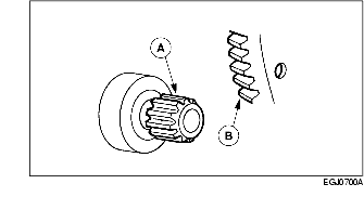
2. Check the wear patterns on the (A) starter drive gear and the (B) flywheel ring gear. If the wear pattern is normal, install the starter motor. (See STARTER REMOVAL/INSTALLATION [YF (2.0L Zetec)].)
3. If the (A) starter drive gear and the (B) flywheel ring gear are not fully meshing and the starter drive gears are scored or damaged, install a new starter motor. (See STARTER REMOVAL/INSTALLATION [YF (2.0L Zetec)].) If necessary, install a new flywheel.