1. Certain axle and driveline malfunction symptoms are also common to the engine, transaxle, wheel bearings, tires, and other parts of the vehicle. For this reason, be sure that the cause of the malfunction is in the axle before adjusting, repairing, or installing any new parts.
1. Lift up the vehicle on a frame hoist and rotate the propeller shaft by hand. Inspect for rough operation or seizure of the U-joint. Inspect for rough operation of the U-joint and sticking of the U-joint and the CV-joint. Install a new propeller shaft if it shows signs of sticking, excessive wear, or incorrect installation. (See PROPELLER SHAFT REMOVAL/INSTALLATION.)
1. Rotate the propeller shaft by hand. If the bearing shows signs of roughness or is noisy, install a new propeller shaft. (See PROPELLER SHAFT REMOVAL/INSTALLATION.)
1. A gear-driven unit will produce a certain amount of noise. Some noise is acceptable and audible at certain speeds or under various driving conditions such as a newly paved blacktop road. Slight noise is not detrimental to the operation of the axle and is considered normal.
Question the customer
1. Clean up the leaking area enough to identify the exact cause.
2. A plugged axle housing vent can cause excessive pinion seal lip wear due to internal pressure buildup.
1. A plugged vent will cause excessive seal lip wear due to internal pressure buildup. If a leakage occurs, inspect the vent. If the vent cannot be cleared, install a new vent.
1. Leakage at the axle drive pinion seal originates for the following reasons:
2. Any damage to the seal bore (dings, dents, gouges, or other imperfections) will distort the seal casing and allow leakage past the outer edge of the axle drive pinion seal.
3. The axle drive pinion seal can be torn, cut, or gouged if it is not installed carefully. The spring that holds the axle drive pinion seal against the pinion flange may be removed and allow leakage past the lip.
4. A new pinion flange must be installed if any of these conditions exist.
5. Metal chips trapped at the sealing lip can cause oil leakage. These can cause a wear groove on the pinion flange and pinion seal wear.
6. When seal leakage occurs, install a new seal and inspect the vent to verify that it is clean and free of foreign material.
1. On some high-mileage units, oil may leak past the threads of the pinion nut. This condition can be corrected by installing a new nut and applying threadlock and sealer on the threads and nut face.
1. The propeller shaft pilot bearing housing seals are susceptible to the same kinds of damage as the axle drive pinion seals if incorrectly installed. The seal bore must be clean and the lip handled carefully to avoid cutting or tearing it. The seal journal surface must be free of nicks, gouges, and rough surface texture.
1. Few vibration conditions are caused by the rear axle. When vibration occurs, and if an obvious reason, which indicates the vibration is caused by axle, is not detected, a malfunction caused by NVH is suspected. Detect the part which causes NVH and repair or replace it.
1. Most vibration in the rear end is caused by tires.
2. Vibration is a concern with tires if they are not in correct condition both radially and laterally. Tires are more susceptible to vibration around the limits of radial and lateral runout of the tire and wheel components. In this case, more accurate balancing is required. Wheel and tire runout inspection, and adjustment and balancing are normally done before axle inspection. Refer to section 205-04.
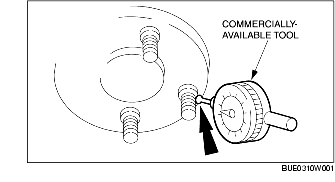
1. Install a commercially-available tool perpendicular to the wheel hub bolt, as close to the hub face as possible. Set the indicator to zero to allow the pointer to deflect either way.
2. Rotate the hub until the next bolt is contacted. Record the measurement and continue until each bolt has been inspected. The difference between the maximum and minimum contact readings will be the total wheel hub bolt pattern runout. The runout must not exceed 0.38 mm.
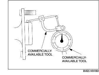
1. Install commercially-available tools as close to the hub face as possible. Set the indicator to zero to allow the pointer to deflect either way.
2. Rotate the hub one full turn and note the maximum and minimum readings. The difference between the maximum and minimum readings will be the total pilot runout. Pilot runout must not exceed 0.15 mm {0.006 in}.
1. Install a commercially-available tool on the wheel hub face, as close to the outer edge as possible. Set the indicator to zero to allow the pointer to deflect either way.
2. Rotate the hub one full turn and note the maximum and minimum readings. The difference between the maximum and minimum readings will be the total face runout. The runout must not exceed 0.254 mm {0.010 in}.
1. Driveline vibration exhibits a higher frequency and lower amplitude than does high-speed shake. Driveline vibration is directly related to the speed of the vehicle and is usually noticed at various speed ranges. Driveline vibration can be perceived as a tremor in the floorpan or is heard as a rumble, hum, or boom. Driveline vibration can exist in all drive modes, but may exhibit different symptoms depending upon whether the vehicle is accelerating, decelerating, floating, or coasting. Inspect the driveline angles if the vibration is particularly noticeable during acceleration or deceleration, especially at lower speeds. Driveline vibration can be duplicated on the lift or the jack stands. When performing test on the lift, the suspension lower arms must be supported with jack stands to make sure the drive shaft maintain the correct ride height. The brakes may need to be applied lightly in order to simulate road resistance.