1. Disconnect the negative battery cable.
2. Remove the battery and battery tray. (See BATTERY REMOVAL/INSTALLATION [YF (2.0L Zetec)].) (See BATTERY REMOVAL/INSTALLATION [L3, AJ (3.0L Duratec)].)
3. Disconnect the crankcase vent hose and MAF sensor connector.
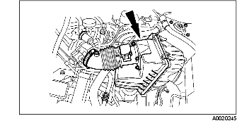
4. Remove the air hose and air cleaner cover.
5. Disconnect the transaxle wiring harness connector and TR switch connector.
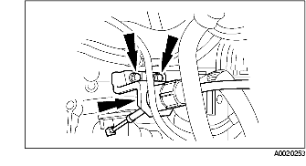
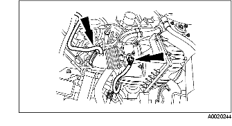
6. Disconnect the selector cable.
7. Remove the selector cable and bracket, then position them out of the way.
8. Remove the vent tube hose.
9. Lift up the vehicle.
10. Remove both front wheels. (See WHEEL AND TIRE REMOVAL/INSTALLATION.)
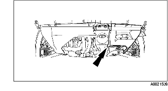
11. Remove the splash shield.
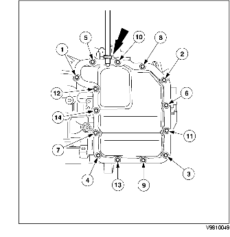
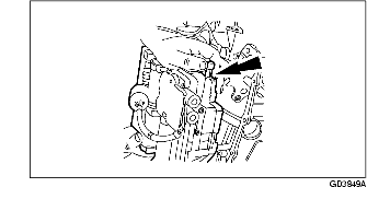
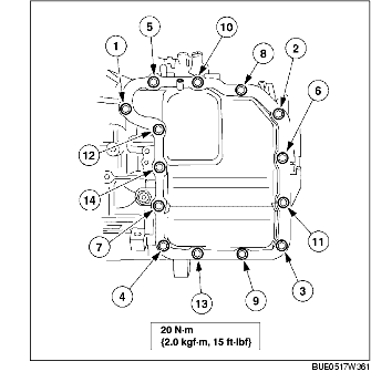
12. Remove the bolts in the order as shown in the figure, and then remove the main control cover.
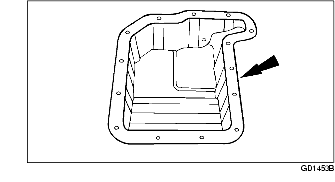
13. Remove the main control cover gasket.
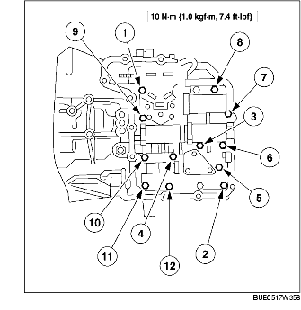
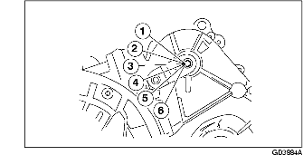
14. Remove the main control valve body bolts in the order as shown in the figure.
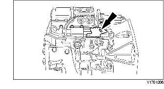
15. Lift the main control valve body while disconnecting the manual valve link.
16. Depress the retaining tabs and push the solenoid valve body connector down through the transaxle case.
17. Make sure the manual valve control lever does not fall out of the main control valve body while removing from the vehicle.
1. Install the manual control valve.
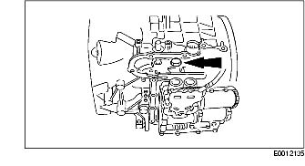
2. Inspect the wiring harness connector O-ring of the solenoid valve body for damage.
3. Push the solenoid valve body wiring harness connector into the case.
4. Connect the manual valve link to the main control valve body.
5. Install the main control valve body and tighten the bolts in the order as shown in the figure.
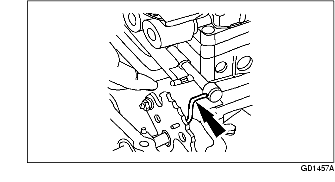
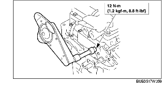
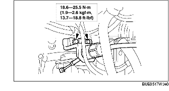
6. Loosen the nut on the ball stud for the manual valve detent lever actuating rod component.
7. Remove the manual control lever outer component bolt.
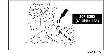
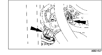
8. Using the SST and pin, align the shifter shaft.
9. Rotate the manual valve detent lever component to the D range.
10. Tighten the nut on the ball and remove the SST.
11. Tighten the detent nut. Rotate back to the D range and inspect the adjustment.
12. Using the SST and pin, align the shifter shaft.
13. Install the manual control lever.
14. Install and rotate the manual valve detent lever component to the N position.
15. Install a new gasket on the main control cover.
16. Install the main control cover, and tighten the bolts in the order as shown in the figure.
17. Install the splash shield.
18. Install the front wheel (LH). (See WHEEL AND TIRE REMOVAL/INSTALLATION.)
19. Lower the vehicle.
20. Install the selector cable and bracket.
21. Connect the selector cable.
22. Clean out any obstructions in the vent tube hose using low air pressure.
23. Install the vent tube hose and clamp.
24. Connect the transaxle wiring harness connector, and TR switch connector.
25. Install the air hose and air cleaner cover.
26. Connect the crankcase vent hose and MAF sensor connector.
27. Verify that there is no blockage or kinks, and the vent hose routing is correct.
28. Install the battery and battery tray. (See BATTERY REMOVAL/INSTALLATION [YF (2.0L Zetec)].) (See BATTERY REMOVAL/INSTALLATION [L3, AJ (3.0L Duratec)].)
29. Connect the negative battery cable.
30. Inspect the ATF level and add Mercon®ATF if necessary.
31. Start the engine and shift the selector lever and pause momentarily in each shift position while depressing the brake pedal. Add ATF if necessary.