|
STEP
|
INSPECTION
|
ACTION
|
|
|---|---|---|---|
|
1
|
DTC INSPECTION
Is the DTC displayed?
• B1300 or B1310
|
Yes
|
Go to the next step.
|
|
No
|
Go to Step 4.
|
||
|
2
|
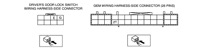
INSPECT DRIVER-SIDE DOOR LOCK SWITCH POWER SUPPLY CIRCUIT FOR SHORT CIRCUIT
Disconnect the GEM connector (26-pin).
Measure the resistance between GEM connector terminal 2T (harness-side) and ground.
Is the resistance 10,000 ohms or more?
|
Yes
|
Go to Step 4.
|
|
No
|
Go to the next step.
|
||
|
3
|
INSPECT DRIVER-SIDE DOOR LOCK SWITCH CIRCUIT FOR SHORT CIRCUIT
Disconnect the driver-side door lock switch connector.
Measure the resistance between driver-side door lock switch connector terminal E and ground.
Is the resistance 10,000 ohms or more?
|
Yes
|
Install a new driver-side door lock switch.
Inspect the system for normal operation.
|
|
No
|
Go to the next step.
|
||
|
4
|
INSPECT DRIVER-SIDE DOOR LOCK SWITCH CIRCUIT FOR SHORT TO B+
Turn the ignition switch to the ON position.
Measure the voltage between GEM connector terminal 2T (harness-side) and ground.
Is there voltage?
|
Yes
|
Repair the circuit.
Inspect the system for normal operation.
|
|
No
|
Go to the next step.
|
||
|
5
|
INSPECT UNLOCK SIGNAL INPUT TO GEM
While pressing the UNLOCK button of the door lock switch, measure the resistance between GEM connector terminal 2T (harness-side) and ground.
Turn the ignition switch to the LOCK position.
Is the resistance less than 5 ohms?
|
Yes
|
Go to Step 8.
|
|
No
|
Go to the next step.
|
||
|
6
|
INSPECT DRIVER-SIDE DOOR LOCK SWITCH GROUND
Disconnect the driver-side door lock switch connector.
Measure the resistance between driver-side door lock switch connector terminal G (harness-side) and ground.
Is the resistance less than 5 ohms?
|
Yes
|
Go to the next step.
|
|
No
|
Repair the circuit.
Inspect the system for normal operation.
|
||
|
7
|
INSPECT DRIVER-SIDE DOOR LOCK SWITCH CIRCUIT FOR OPEN CIRCUIT
Measure the resistance between driver-side door lock switch connector terminal E (harness-side) and GEM connector terminal 2T (harness-side).
Is the resistance less than 5 ohms?
|
Yes
|
Install a new driver-side door lock switch.
Inspect the system for normal operation.
|
|
No
|
Repair the circuit. Inspect the system for normal operation.
|
||
|
8
|
INSPECT GEM FOR NORMAL OPERATION
Disconnect the GEM connector.
• Corrosion
• Terminal separation
Connect all the connectors and verify that their positions are correct.
Operate the system and inspect for any malfunction.
Is there any malfunction?
|
Yes
|
Install a new GEM. (See GENERIC ELECTRONIC MODULE (GEM) REMOVAL/INSTALLATION.)
Clear the DTC and perform the DTC inspection.
|
|
No
|
The malfunction may result from loose connectors or corrosion. Reverify that the system operates normally.
Clear the DTC and perform the DTC inspection.
|
||
|
|
|||