|
STEP
|
INSPECTION
|
ACTION
|
|
|---|---|---|---|
|
1
|
DTC INSPECTION
Is the DTC displayed?
|
Yes
|
If DTC B2100 is displayed, go to Step 2.
If DTC B2104 is displayed, go to Step 7.
|
|
No
|
If the door-side door key cylinder switch does not operate, go to Step 4.
If the liftgate door key cylinder switch does not operate, go to Step 9.
|
||
|
2
|
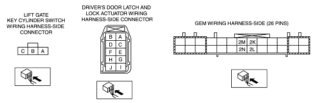
INSPECT DRIVER-SIDE DOOR KEY CYLINDER
Disconnect the driver-side door latch and lock actuator connector.
Measure the resistance between driver-side door latch and lock actuator connector terminal H (harness-side) and ground, and driver-side door latch and lock actuator connector terminal F and ground.
Is the resistance 10,000 ohms or more?
|
Yes
|
Go to Step 4.
|
|
No
|
Go to the next step.
|
||
|
3
|
INSPECT DRIVER-SIDE DOOR KEY CYLINDER CIRCUIT FOR SHORT TO GROUND
Measure the resistance between GEM connector terminal 2N (harness-side) and ground, and GEM connector terminal 2L and ground.
Is the resistance 10,000 ohms or more?
|
Yes
|
Install a new driver-side front door latch and lock actuator. (See FRONT DOOR LATCH AND LOCK ACTUATOR REMOVAL/INSTALLATION.)
Clear the DTC and perform the DTC inspection.
|
|
No
|
Repair the circuit.
Inspect the system for normal operation.
|
||
|
4
|
INSPECT DRIVER-SIDE DOOR KEY CYLINDER CIRCUIT FOR SHORT TO B+
Turn the ignition switch to the ON position.
Measure the voltage between GEM connector terminal 2N (harness-side) and ground, and GEM connector terminal 2L (harness-side) and ground.
Is there voltage?
|
Yes
|
Repair the circuit.
Inspect the system for normal operation.
|
|
No
|
Go to the next step.
|
||
|
5
|
INSPECT DRIVER-SIDE DOOR KEY CYLINDER SWITCH GROUND
Measure the resistance between driver-side door latch and lock actuator terminal E (harness-side) and ground.
Is the resistance less than 5 ohms?
|
Yes
|
Go to the next step.
|
|
No
|
Repair the circuit.
Inspect the system for normal operation.
|
||
|
6
|
INSPECT DRIVER-SIDE DOOR KEY CYLINDER CIRCUIT FOR OPEN CIRCUIT
Inspect the resistance between GEM connector terminal 2N (harness-side) and driver-side door latch and lock actuator connector terminal H (harness-side), and GEM connector terminal 2L (harness-side) and driver-side door latch and lock actuator terminal F (harness-side).
Is the resistance less than 5 ohms between both terminals and ground?
|
Yes
|
Go to Step 12.
|
|
No
|
Repair the suspected circuit.
Inspect the system for normal operation.
|
||
|
7
|
INSPECT LIFTGATE KEY CYLINDER SWITCH CIRCUIT FOR SHORT CIRCUIT
Disconnect the GEM connector (26-pin).
Measure the resistance between GEM connector terminal 2K (harness-side) and ground, and GEM connector terminal 2M (harness-side) and ground.
Is the resistance 10,000 ohms or more?
|
Yes
|
Go to Step 9.
|
|
No
|
Go to the next step.
|
||
|
8
|
INSPECT LIFTGATE KEY CYLINDER SWITCH
Measure the resistance between GEM connector terminal 2K (harness-side) and ground, and GEM connector terminal 2M (harness-side) and ground.
Is the resistance 10,000 ohms or more?
|
Yes
|
Install a new liftgate key cylinder switch.
Clear the DTC and perform the DTC inspection.
|
|
No
|
Repair the suspected circuit.
Inspect the system for normal operation.
|
||
|
9
|
INSPECT LIFTGATE KEY CYLINDER SWITCH CIRCUIT FOR SHORT TO B+
Turn the ignition switch to the ON position.
Measure the voltage between GEM connector terminal 2K (harness-side) and ground, and the voltage between GEM connector terminal 2M (harness-side) and ground.
Is there voltage?
|
Yes
|
Repair the circuit.
Inspect the system for normal operation.
|
|
No
|
Go to the next step.
|
||
|
10
|
INSPECT LIFTGATE KEY CYLINDER SWITCH CIRCUIT FOR OPEN CIRCUIT
Disconnect liftgate key cylinder switch connector. Measure the resistance between GEM connector terminal 2K (harness-side) and liftgate key cylinder switch connector terminal C (harness-side), and GEM connector terminal 2M (harness-side) and liftgate key cylinder switch connector terminal A (harness-side).
Is the resistance less than 5 ohms between both terminals?
|
Yes
|
Go to the next step.
|
|
No
|
Repair the suspected circuit.
Inspect the system for normal operation.
|
||
|
11
|
INSPECT LIFTGATE KEY CYLINDER SWITCH GROUND
Measure the resistance between liftgate key cylinder switch connector terminal B (harness-side) and ground.
Is the resistance less than 5 ohms?
|
Yes
|
Install a new liftgate key cylinder switch.
Inspect the system for normal operation.
|
|
No
|
Repair the circuit.
Inspect the system for normal operation.
|
||
|
12
|
INSPECT GEM FOR NORMAL OPERATION
Disconnect the GEM connector.
Inspect for the following items:
• Corrosion
• Terminal separation
Connect all the connectors and verify that their positions are correct.
Operate the system and inspect for any malfunction.
Is there any malfunction?
|
Yes
|
Install a new GEM. (See GENERIC ELECTRONIC MODULE (GEM) REMOVAL/INSTALLATION.)
Clear the DTC and perform the DTC inspection.
|
|
No
|
Verify that the system operates normally at this stage. The malfunction may result from loose connectors or corrosion.
Clear the DTC and perform the DTC inspection.
|
||
|
|
|||