|
STEP
|
INSPECTION
|
ACTION
|
|
|---|---|---|---|
|
1
|
INSPECT DOUBLE LOCK OPERATION
Remove the key from the ignition switch.
Make sure all doors and liftgate and hood are closed.
Lock the doors with the key cylinder switch or transmitter. Within three seconds, activate lock again.
Is the double lock operation inoperative at all actuators?
|
Yes
|
Go to Step 3.
|
|
No
|
Go to the next step.
|
||
|
2
|
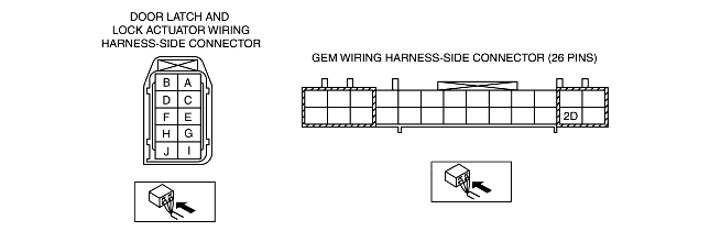
INSPECT DOOR LATCH AND LOCK ACTUATOR CIRCUIT FOR OPEN CIRCUIT
Disconnect the inoperative door latch and lock actuator and GEM connector (26-pin).
Measure the resistance between GEM connector terminal 2D (harness-side) and suspect door latch and lock actuator connector terminal C (harness-side).
Is the resistance less than 5 ohms?
|
Yes
|
Install a new door latch and lock actuator. (See FRONT DOOR LATCH AND LOCK ACTUATOR REMOVAL/INSTALLATION.)(See REAR DOOR LATCH AND LOCK ACTUATOR REMOVAL/INSTALLATION.)
Inspect the system for normal operation.
|
|
No
|
Repair the circuit.
Inspect the system for normal operation.
|
||
|
3
|
INSPECT DOOR LATCH PID
While opening and closing the doors, use the display to inspect the GEM PIDs for the driver and passenger-side door latch switch, using the display.
Do the PIDs vary according to the lock/unlock status?
|
Yes
|
Go to the next step.
|
|
No
|
Malfunction in the door latch switch system
|
||
|
4
|
INSPECT GEM CIRCUIT FOR SHORT TO B+
Disconnect the GEM connector (26-pin).
Measure the voltage between GEM connector terminal 2D (harness-side) and ground.
Is there voltage?
|
Yes
|
Repair the circuit.
Inspect the system for normal operation.
|
|
No
|
Go to the next step.
|
||
|
5
|
INSPECT GEM CIRCUIT FOR SHORT TO GROUND
Measure the resistance between GEM connector terminal 2D (harness-side) and ground.
Is the resistance 10,000 ohms or more?
|
Yes
|
Go to the next step.
|
|
No
|
Repair the circuit.
Inspect the system for normal operation.
|
||
|
6
|
INSPECT DRIVER-SIDE DOOR LATCH SWITCH CIRCUIT FOR OPEN CIRCUIT
Disconnect the driver-side door latch and lock actuator connector.
Measure the resistance between GEM connector terminal 2D (harness-side) and driver-side door latch and lock actuator connector terminal C (harness-side).
Is the resistance less than 5 ohms?
|
Yes
|
Go to the next step.
|
|
No
|
Repair the circuit.
Inspect the system for normal operation.
|
||
|
7
|
INSPECT GEM FOR NORMAL OPERATION
Disconnect the GEM connector.
Inspect for the following items:
• Corrosion
• Terminal separation
Connect all the connectors and verify that their positions are correct.
Operate the system and inspect for any malfunction.
Is there any malfunction?
|
Yes
|
Install a new GEM. (See GENERIC ELECTRONIC MODULE (GEM) REMOVAL/INSTALLATION.)
Clear the DTC and perform the DTC inspection.
|
|
No
|
Verify that the system operates normally at this stage. The malfunction may result from loose connectors or corrosion.
Clear the DTC and perform the DTC inspection.
|
||
|
|
|||